Fiber optic dust cap assembly and method

a fiber optic and dust cap technology, applied in the field of dust caps, can solve the problems of increasing technician time, difficult for technicians to grip the end of the dust cap during the removal, and affecting the removal effect so as to facilitate the removal facilitate the management of the dust cap, and facilitate the effect of removal

Inactive Publication Date: 2010-05-27
CORNING OPTICAL COMM LLC
View PDF5 Cites 17 Cited by
  • Summary
  • Abstract
  • Description
  • Claims
  • Application Information

AI Technical Summary

Benefits of technology

[0009]Embodiments disclosed in the detailed description include a fiber optic dust cap assembly for protecting fiber optic components. The protected fiber optic components may include, but are not limited to fiber optic adapters and fiber optic connectors. The fiber optic dust cap assembly includes a plurality of dust caps each coupled to a lanyard. Each of the plurality of dust caps is configured for insertion into a fiber optic component. The lanyard is configured to facilitate management of the dust caps. This includes facilitating removal of the dust caps from fiber optic components. Each of the dust caps among the plurality of dust caps may be removed by pulling on the lanyard. The lanyard may facilitate removal of each of the plurality of dust caps in one pulling action. Also, by the plurality of dust caps being connected to the lanyard, the plurality of dust caps remain coupled to the lanyard after removal.

Problems solved by technology

Removing dust caps takes considerable technician time and cost.
The small size of dust caps also makes it difficult for a technician to grip the end of the dust cap during removal.
The difficulty in removing the dust caps may also increase technician time.
Also, as a technician removes the dust caps, due to the small size of the dust caps, the technician may be inclined to misplace or simply drop the dust caps in the equipment rack or on the floor, such that over time, a myriad of dust caps may accumulate.

Method used


Image

  • Fiber optic dust cap assembly and method
  • Fiber optic dust cap assembly and method
  • Fiber optic dust cap assembly and method

Examples


Embodiment Construction

[0026]Reference will now be made in detail to the preferred embodiments of the invention, examples of which are illustrated in the accompanying drawings, in which some, but not all embodiments of the invention are shown. Indeed, the invention may be embodied in many different forms and should not be construed as limited to the embodiments set forth herein; rather, these embodiments are provided so that this disclosure will satisfy applicable legal requirements. Whenever possible, like reference numbers will be used to refer to like components or parts.

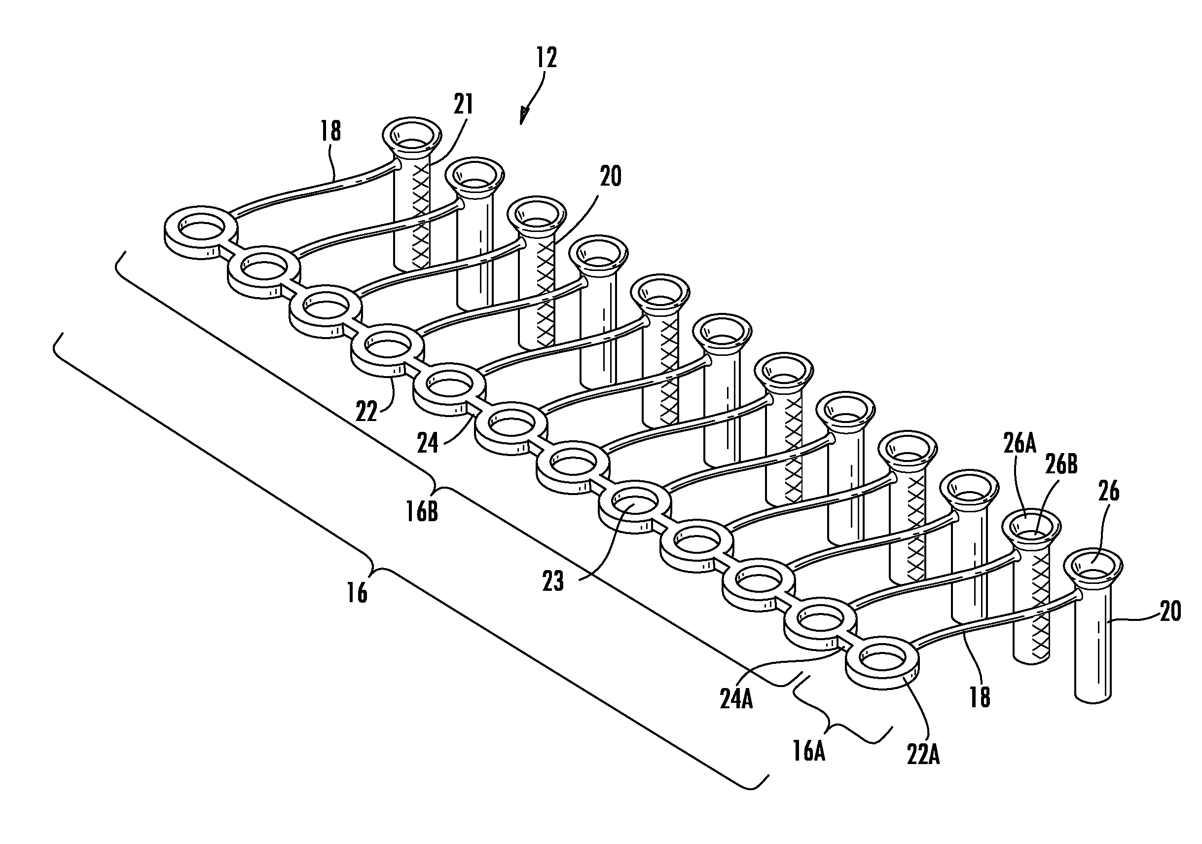
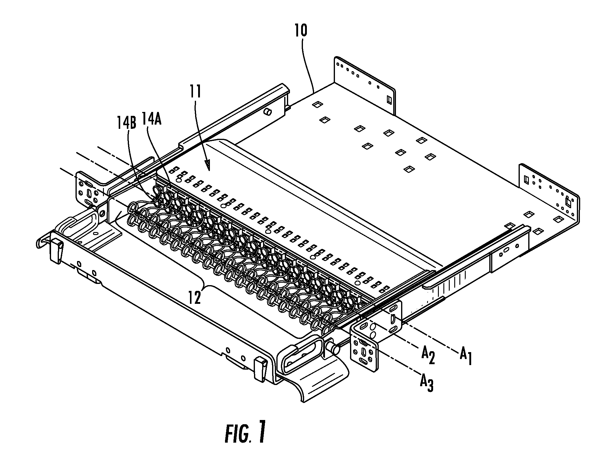
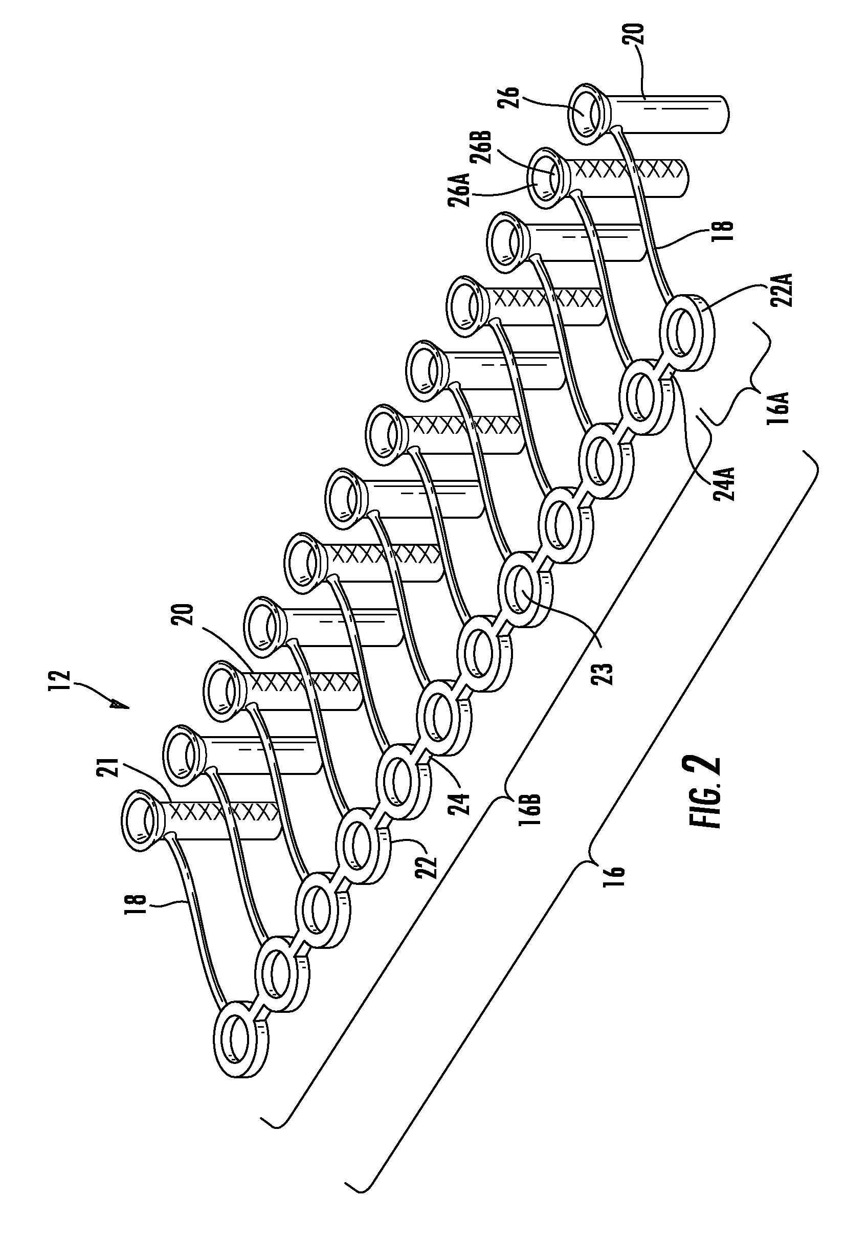
[0027]Embodiments disclosed in the detailed description include a fiber optic dust cap assembly for protecting fiber optic components. The protected fiber optic components may include, but are not limited to fiber optic adapters and fiber optic connectors. The fiber optic dust cap assembly includes a plurality of dust caps each coupled to a lanyard. Each of the plurality of dust caps is configured for insertion into a fiber optic compo...


PUM


Abstract

A fiber optic dust cap assembly for protecting fiber optic components is provided. The protected fiber optic components may include fiber optic adapters and fiber optic connectors. The fiber optic dust cap assembly includes a plurality of dust caps each coupled to a lanyard. Each of the plurality of dust caps is configured for insertion into a fiber optic component. The lanyard is configured to facilitate management of the dust caps. The lanyard is also configured to facilitate removal of the dust caps from the fiber optic components. Each of the dust caps among the plurality of dust caps may be removed by pulling on the lanyard. The lanyard may also facilitate removal of each of the plurality of dust caps in one pulling action. Additionally, by the plurality of dust caps being connected to the lanyard, the plurality of dust caps coupled to the lanyard remain together after removal.

Description

CROSS-REFERENCE TO RELATED APPLICATIONS[0001]This application claims the benefit of priority under 35 U.S.C. §119(e) of U.S. Provisional Application Ser. No. 61 / 117,394 filed on Nov. 24, 2008.FIELD OF THE DISCLOSURE[0002]The technology of the disclosure relates to a dust cap for fiber optic components, including fiber optic adapters and connectors.TECHNICAL BACKGROUND[0003]Benefits of optical fiber include extremely wide bandwidth and low noise operation. Because of these benefits, optical fiber is increasingly being used for a variety of applications, including but not limited to broadband voice, video, and data transmission. Fiber optic networks employing optical fiber are being developed and used to deliver voice, video, and data transmissions to subscribers over both private and public networks. These fiber optic networks often include separated connection points at which it is necessary to link optical fibers in order to provide “live fiber” from one connection point to another...

Claims


Application Information

Patent Timeline
Patent Type & Authority Applications(United States)
IPC IPC(8): G02B7/00
CPCG02B6/4452G02B6/3849
Inventor COOKE, TERRY LEEDEAN, JR., DAVID LEEKLAVUHN, TORY ALLENMABRY, III, CLYDE BENTON
Owner CORNING OPTICAL COMM LLC
Why Eureka
Try Eureka