
Method for controlling a work machine during operation in a repeated work cycle

a work machine and work cycle technology, applied in the field of repeated work cycle control, can solve the problems of work machine reaction and wear in response, and achieve the effects of reducing transmission wear, improving fuel efficiency, and increasing off-road drivingability

Active Publication Date: 2010-05-27
VOLVO CONSTR EQUIP
View PDF6 Cites 69 Cited by
  • Summary
  • Abstract
  • Description
  • Claims
  • Application Information

AI Technical Summary

Benefits of technology

[0008]It is desirable to reduce fuel consumption and / or increase productivity, ie transporting as much material in as short time as possible in a cost-efficient way. Further, the transportation should preferably be performed with due regard to environmental factors.
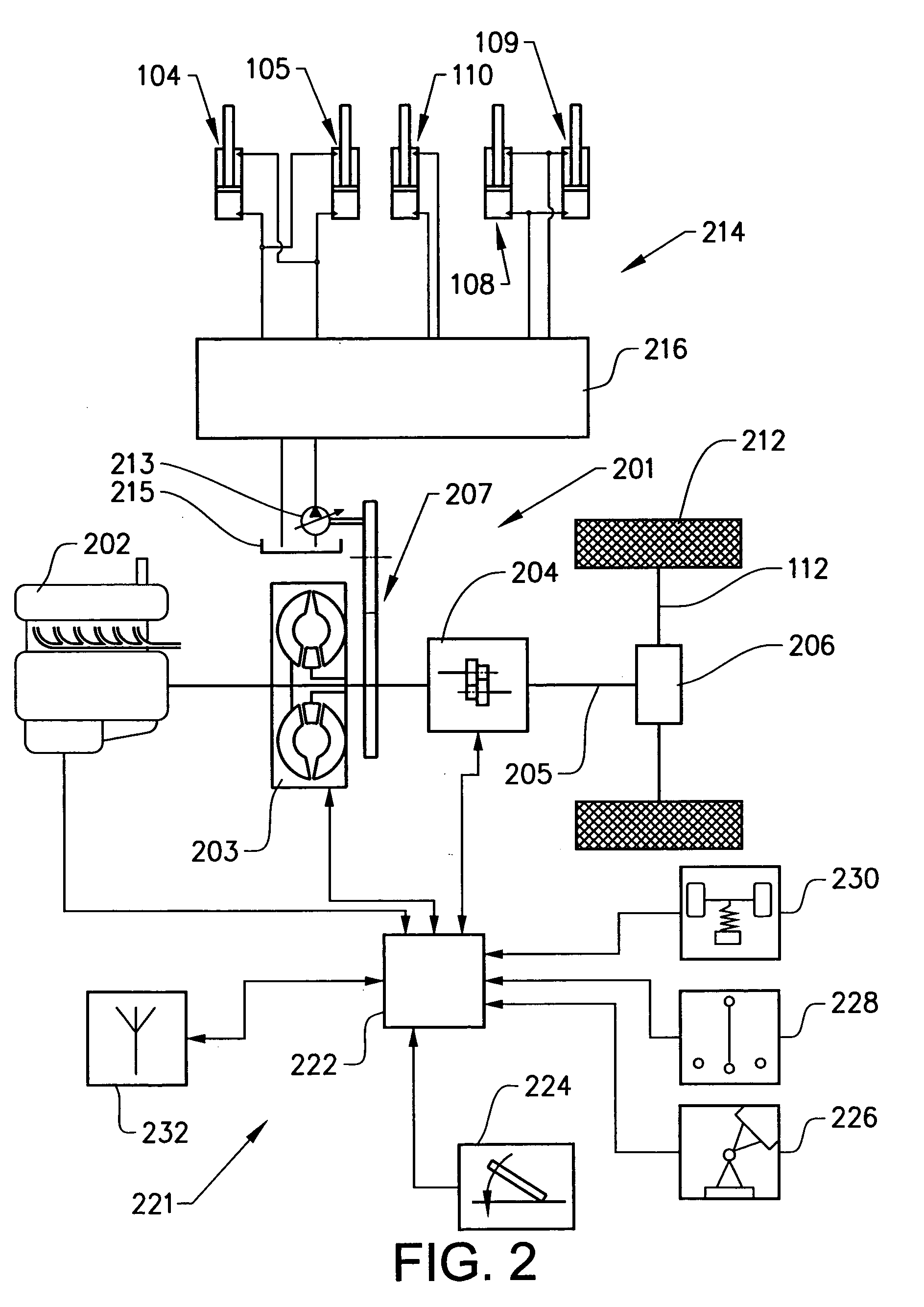
[0025]Thus, for a work machine with an automatic gearbox a so-called gear mode or gear function is automatically selected in response to the established control strategy. The gear modes may differ in that changing to a higher gear, changing up, is carried out at different minimum engine speeds, for changing between corresponding gears, and changing to a lower gear is carried out at different minimum vehicle speeds. By automatically controlling the gearbox in response to the established sequence of control events, fuel efficiency can be improved. Further, wear on the transmission can be reduced.
[0026]According to a further preferred embodiment, the control strategy comprises information regarding a differential gear operation and the method comprising the step of controlling the differential gear. An articulated hauler comprises a longitudinal and / or transverse differential gear with an associated differential gear lock mechanism. Such differential gear lock mechanisms are used to increase the off road driveability, but they are often engaged also when they are not needed. By automatically controlling the activation of the differential gear lock mechanisms in response to the established sequence of control events, fuel efficiency can be improved and less wear on the components can be achieved, leading to a longer life.

Problems solved by technology

Further, different models of a work machine may react differently when the work cycle is performed.
Further, different individuals in a fleet may be of different age and have different operation history with a resulting wear in response thereto etc.

Method used


Image

  • Method for controlling a work machine during operation in a repeated work cycle
  • Method for controlling a work machine during operation in a repeated work cycle
  • Method for controlling a work machine during operation in a repeated work cycle

Examples


Embodiment Construction

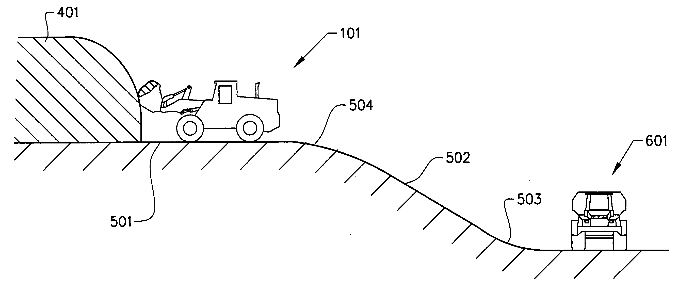
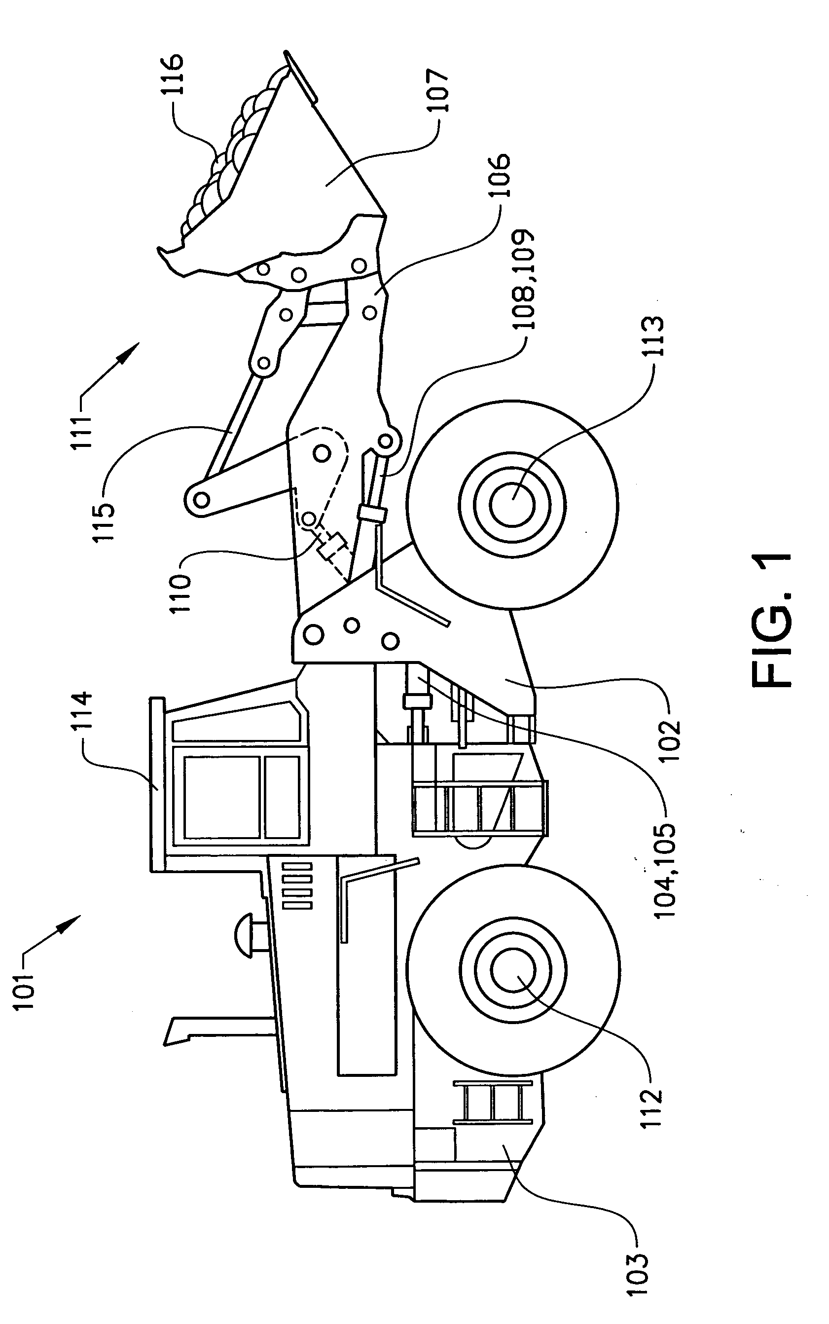
[0039]FIG. 1 shows a frame-steered work machine constituting a wheel loader 101. The body of the wheel loader 101 comprises a front body section 102 and a rear body section 103, which sections each has a pair of half shafts 112,113. The rear body section 103 comprises a cab 114. The body sections 102,103 are connected to each other in such a way that they can pivot in relation to each other around a vertical axis by means of two first actuators in the form of hydraulic cylinders 104,105 arranged between the two sections. The hydraulic cylinders 104,105 are thus arranged one on each side of a horizontal centerline of the vehicle in a vehicle traveling direction in order to turn the wheel loader 101.

[0040]The wheel loader 101 comprises an equipment 111 for handling objects or material. The equipment 111 comprises a load-arm unit 106 and an implement 107 in the form of a bucket fitted on the load-arm unit. A first end of the load-arm unit 106 is pivotally connected to the front vehicle...


PUM


Abstract

A method is provided for controlling a work machine during operation in a repeated work cycle including the steps of establishing a control strategy on the basis of at least one condition that varies in the course of the work cycle, and controlling at least one device in a work machine power transmission system in response to the established control strategy.

Description

BACKGROUND AND SUMMARY[0001]The present invention relates to a method for controlling a work machine during operation in a repeated work cycle.[0002]The term “work machine” comprises different types of material handling vehicles like construction machines, such as a wheel loader and a dump truck (such as an articulated hauler). A work machine is provided with a bucket, container or other type of work implement for carrying / transporting a load. Further terms frequently used for work machines are “earth-moving machinery” and “off-road work machines”.[0003]In connection with transportation of heavy loads, e.g. in contracting work, work machines are frequently used. A work machine may be operated with large and heavy loads in areas where there are no roads, for example for transports in connection with road or tunnel building, sand pits, mines and similar environments.[0004]The term work cycle comprises a route of the work machine (ie the work cycle travel path) and / or a movement of the...

Claims


Application Information

Patent Timeline
IPC IPC(8): G06F7/00B60W30/18B60W10/10B60W10/12
CPCB60W10/11B60W10/12B60W30/18E02F9/2253B60W2550/402E02F9/2025E02F9/2045B60W2530/10B60W2556/50
Inventor DERSJO, JANBRATTBERG, BJORN
Owner VOLVO CONSTR EQUIP
Learn More