Design and fabrication of a local concentrator system

a technology of local concentrators and fabrication methods, applied in the field of solar energy, can solve the problems of reducing the efficiency of the system and increasing the cost of manufacture, and achieve the effect of modular design

Active Publication Date: 2010-06-03
RENESSELAER POLYTECHNIC INST
View PDF10 Cites 16 Cited by
  • Summary
  • Abstract
  • Description
  • Claims
  • Application Information

AI Technical Summary

Benefits of technology

[0012]According to another embodiment of the invention, there is provided an apparatus for collecting solar energy. The apparatus comprises an array of spherical concentrators held by a grid mesh and positioned above an array of photovoltaic cells and heat sinks. The spherical concentrators allow light to be concentrated independent of the angle from which it enters, thus making tracking of the sun unnecessary. Furthermore, the array of spherical concentrators can be arranged above any desired arrangement or design of PV cells, thus making the resulting apparatus modular in design. The spherical concentrators can also be composed of a variety of transparent materials including glass and plastic. The size of the spherical concentrators will only be limited by the amount of heat dissipation needed in the specific application.

Problems solved by technology

However there are a few problems that need to be addressed for concentrator technology: (a) active cell cooling becomes absolutely necessary due to higher temperatures by power concentration and (b) the entire concentrator module needs to be continuously rotated during the day to track and face the sun as it traverses the sky during the day.
This latter problem is a significant one, since solar concentrators are required to track the movement of the sun, this decreases the efficiency of the system since it can only collect light from a particular angle at any one time.
Furthermore the requirement of tracking the sun increases the costs of manufacture significantly.

Method used


Image

  • Design and fabrication of a local concentrator system
  • Design and fabrication of a local concentrator system
  • Design and fabrication of a local concentrator system

Examples


Embodiment Construction

[0027]In the following detailed description of various embodiments, reference is made to the accompanying drawings that form a part hereof, and in which are shown by way of illustration, and not of limitation, specific embodiments in which the subject matter may be practiced. The embodiments illustrated are described in sufficient detail to enable those skilled in the art to practice the teachings disclosed herein. Other embodiments may be utilized and derived therefrom, such that compositional, structural, and logical substitutions and changes may be made without departing from the scope of this disclosure. Examples and embodiments merely typify possible variations. Individual components and functions are optional unless explicitly required, and the sequence of operations may vary. Portions and features of some embodiments may be included in or substituted for those of others. The following description is, therefore, not to be taken in a limiting sense.

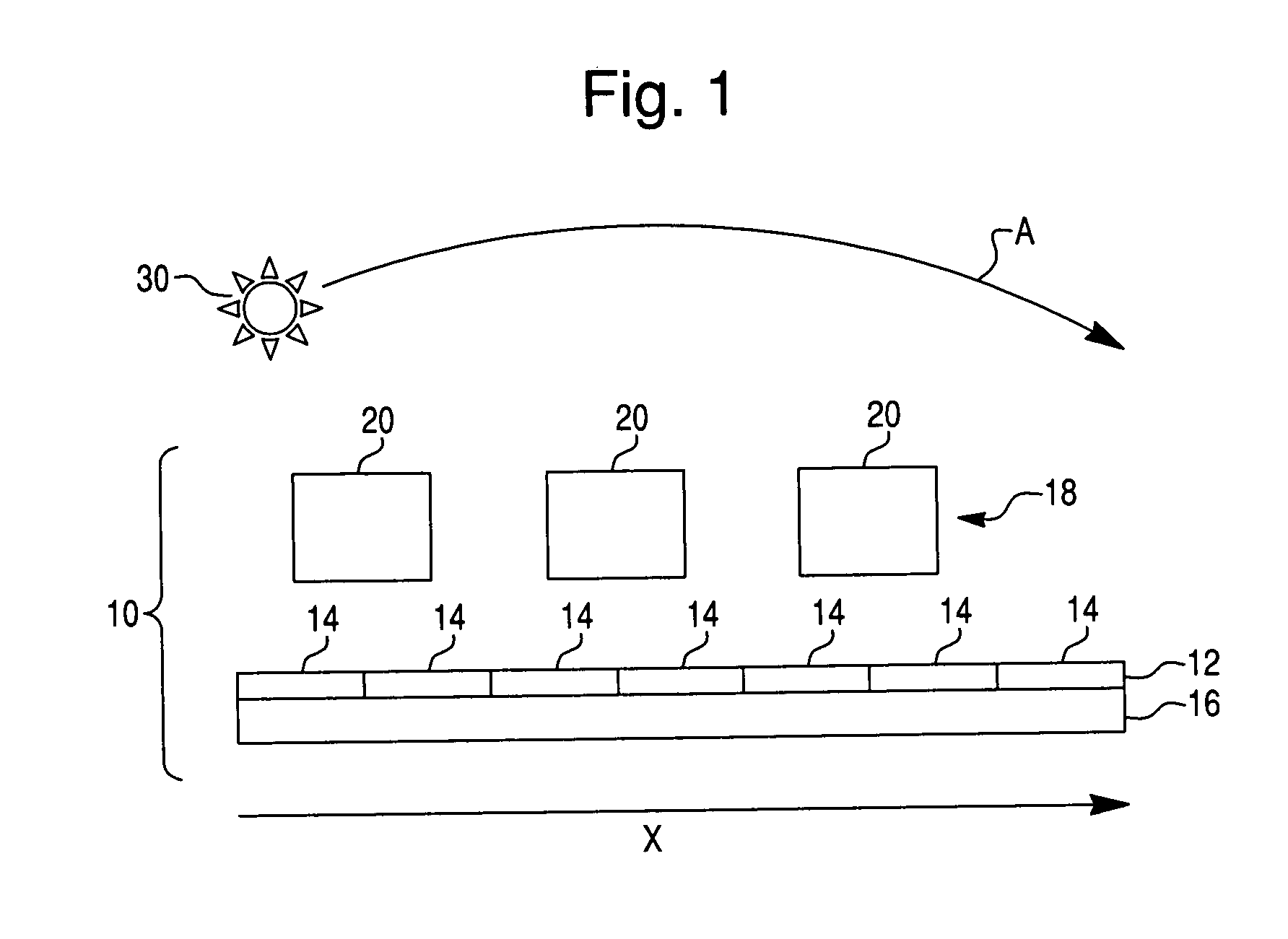
[0028]FIG. 1 illustrates in s...


PUM


Abstract

A local concentrator apparatus is described. The apparatus includes an array of photovoltaic cells arranged along an elongated strip, and one or more optical elements. The one or more optical elements are arranged to direct and optically concentrate sunlight onto the photovoltaic cells such that position that the directed sunlight impinges onto the strip follows a path moving along the strip without the optical elements tracking the sun as the sun traverses the sky during the day.

Description

CROSS-REFERENCE TO RELATED PATENT APPLICATIONS[0001]This application claims priority to U.S. Provisional Application 60 / 948,260 filed on Jul. 6, 2007, which is incorporated by reference in its entirety.BACKGROUND OF THE INVENTION[0002]1. Field of the Invention[0003]The present invention relates to the area of solar energy, and more particularly to a design and fabrication of a high efficiency, low cost, local concentrator type solar photovoltaic (PV) panel and a local concentrator panel.[0004]2. Description of Related Art[0005]It is well known that for PV technology to be viable for wide-spread adoption, there are two primary requirements: cell efficiency of at least 20% and the total system cost enabling a pay-back time of a few months to a couple of years. Unfortunately, most PV technology has problems with either one or both of these requirements.SUMMARY OF THE INVENTION[0006]One object of the invention is to enable the fabrication of high efficiency solar photovoltaic systems th...

Claims


Application Information

Patent Timeline
Patent Type & Authority Applications(United States)
IPC IPC(8): H01L31/052
CPCH01L31/052H01L31/0547H01L31/0543Y02E10/52
Inventor DUTTA, PARTHA
Owner RENESSELAER POLYTECHNIC INST
Why Eureka
Try Eureka