Methane hydrate dissociation accelerating and methane gas deriving system

Active Publication Date: 2010-06-03
JAPAN DRILLING CO LTD +1
View PDF7 Cites 21 Cited by
  • Summary
  • Abstract
  • Description
  • Claims
  • Application Information

AI Technical Summary

Benefits of technology

[0034]The present invention makes use of, as a heat source, the ground heat inexhaustibly present under the ground. Therefore, according to the present invention, the geothermal energy is stably supplied to the methane hydrate layer for a long period without requiring special fuel or the like. It is possible to realize expansion of a methane hydrate dissociation boundary surface by supplying sufficient heat quantity.
[0035]Compared with the heating method of the hot water injecting system, according to the present invention, not only the hot water producing apparatus and the enormous fuel cost but also a heating line from a platform on the sea to wells is unnecessary. Therefore, the present invention is free from a large amount of equipment cost burden related to hot water production on the platform and transportation to the wells.
[0036]According to the present invention, when the partially advantageous functions of the depressurization method and the heating method are used in combination and production control means in two systems are secured, it is possible to effectively perform heat exchange on the dissociation boundary surface below methane hydrate and simultaneously accelerate dissociation in a wide area. Therefore, it is possible to realize leveling of the production behavior curve, improvement of a recovery ratio, and i

Problems solved by technology

The largest problem in the development of methane hydrate is poor economy.
However, it is difficult to substantially improve the productivity with the simple depressurization method regarded as an effective production method at the present point.
A major cause that prevents a productivity improvement in the depressurization method is its insufficient ability of supply

Method used


Image

  • Methane hydrate dissociation accelerating and methane gas deriving system
  • Methane hydrate dissociation accelerating and methane gas deriving system
  • Methane hydrate dissociation accelerating and methane gas deriving system

Examples


Embodiment Construction

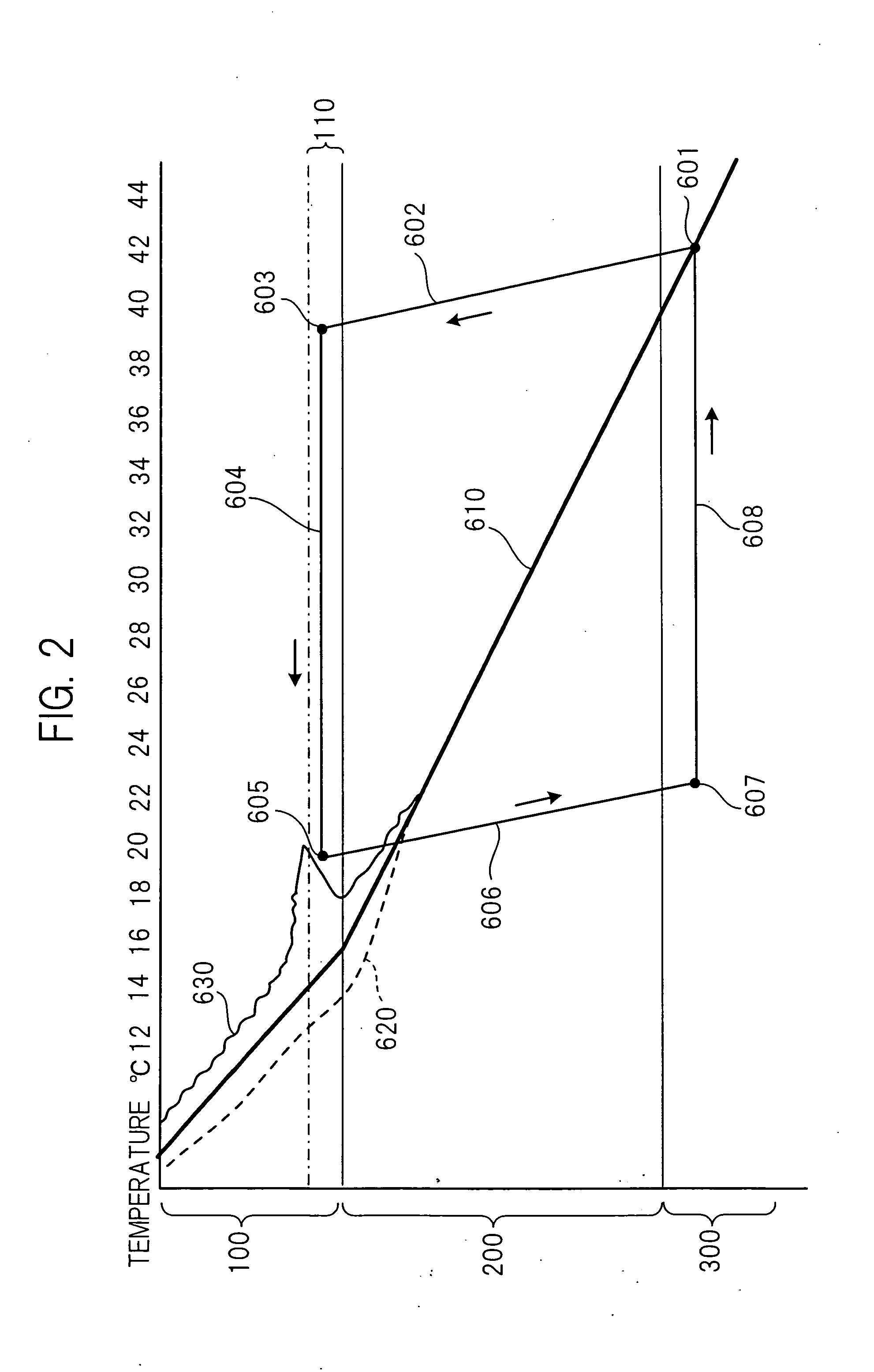
[0048]When it is assumed that the depth of water is 1,000 m, seabed temperature is 4° C., and ground temperature gradient is 3 to 4° C. / 100 m, the ground temperature at 1,000 m below the seabed is expected to be 34 to 44° C. The depth limit of a riser-less drilling work is about 1,500 m below the seabed. The layer pressure is usually low up to near this depth and thus, it is considered that a riser-less low-pressure rotating BOP can be used. When the drilling proceeds deeper, since the full-scale BOP and the riser are necessary in view of safety measures, drilling cost suddenly increases. The limit depth of a deep aquifer that can be economically used is about 1,500 m below the seabed.

[0049]Therefore, concerning the deep aquifer that should be used, comparison and examination are performed in a range of 1,000 m to 1,500 m below the seabed and a sand layer having highest geothermal energy supply ability is selected. Although the drilling cost changes according to depth, since ground ...


PUM


Abstract

It is an object of the present invention to provide a deriving technique with economy and technical difficulty improved without depending on fuel consumption for a heat source when methane gas is derived from a methane hydrate layer. Warm water is pumped up by a pump from an underground aquifer present 1000 to 1500 m below the seabed, geothermal energy is caused to flow through a permeable layer below a methane hydrate layer, a dissociation boundary surface of an un-dissociated area of the methane hydrate layer is dissociated to generate methane gas, the methane gas is led into a production well from peripheral areas and through a gas inlet screen and caused to rise so that the methane gas is collected on the sea.

Description

TECHNICAL FIELD[0001]The present invention relates to a deriving system for methane hydrate.BACKGROUND ART[0002]Recent research and survey results report that it is possible that methane hydrate equivalent to a domestic gas consumption amount for 100 years is present in the area of sea around Japan. The methane hydrate is a potential resource that is abundantly present under the seabed of the deep sea and in which methane and water are solidified in a high pressure and low temperature state.[0003]It is difficult to economically derive the methane hydrate with the present technology because productivity is low. However, on the premise that an inexpensive production method is developed and optimization of production behavior is realized, it is expected that a way of using the methane hydrate as a future energy source will be found.[0004]As means for deriving methane gas from methane hydrate, a depressurization method and a heating method have been proposed. A combined method as a comb...

Claims


Application Information

Patent Timeline
IPC IPC(8): E21B43/00
CPCC10L3/10E21B2043/0115E21B43/24E21B43/01E21B41/0099Y02E10/10
Inventor NAKAMURA, MASAHIROGOTO, SABURONOZAWA, TAKEYOSHIISHIDA, KOZO
Owner JAPAN DRILLING CO LTD
Why Eureka
Try Eureka