Spark plug and manufacturing method thereof
- Summary
- Abstract
- Description
- Claims
- Application Information
AI Technical Summary
Benefits of technology
Problems solved by technology
Method used
Image

Examples
Example
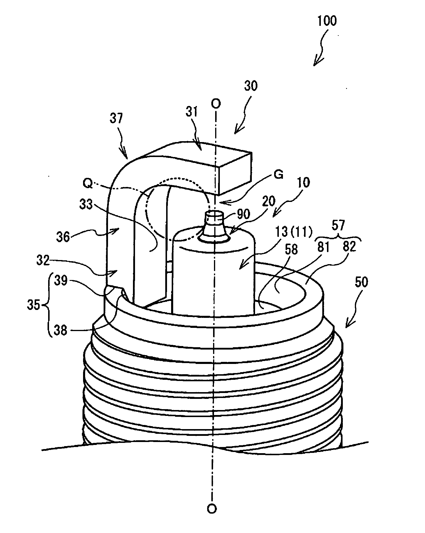
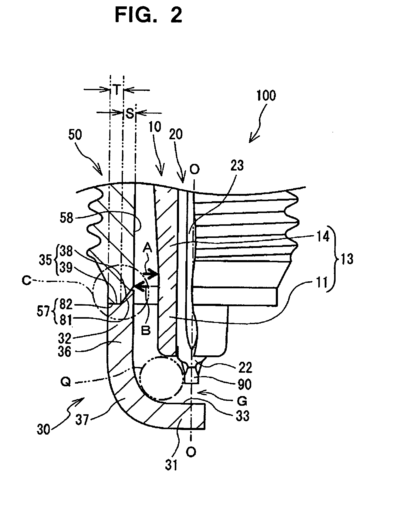
[0044]According to the first embodiment, when the metal shell 50 is joined to the ground electrode 30, the end face 35 is processed so as to correspond to the shape of the front end constituent face 57. More particularly, as shown in FIGS. 2 and 3, in order to correspond to the front end constituent face 57 of the metal shell 50, the end face 35 of the ground electrode 30 is comprised of a corresponding inclined face 38 corresponding to the inclined face 81 and a corresponding flat face 39 corresponding to the flat face 82. Thus, before welding the ground electrode 30 to the metal shell 50, the entire end face 35 of the ground electrode 30 is brought into contact with the front end constituent face 57 of the metal shell 50. As a result, the entire end face 35 at the base 32 side of the ground electrode 30 adjoins the front end constituent face 57 of the metal shell 50 and a contact area therebetween is secured, thereby improving joint strength therebetween.
[0045]The flat face 82 and...
Example
EXAMPLE 1
[0060]The spark plug 100 manufactured in this way can maintain sufficient clearance with specifying a dimension of the virtual sphere Q that is in contact with the inner face 33 of the bending portion 37 of the ground electrode 30 and is neither in contact with the center electrode 20 (including the noble metal tip 90) nor the insulator 10. An evaluation was conducted to confirm the effect of the invention. In this evaluation, several samples of the spark plug were produced in which the magnitude of bending of the ground electrode 30 was differentiated in the gap formation step of the spark plug 100. While maintaining the spark discharge gap G of 0.9 mm, the radius of the virtual sphere Q of each sample was changed by 0.1 mm within the range from 0.7 mm to 1.5 mm. In addition, the bending conditions were changed by shifting a border between the extending portion 36 and the bending portion 37 (a position where the ground electrode 30 starts to bend at the base 32 side), or c...
Example
EXAMPLE 2
[0063]Next, an evaluation for testing the joint strength when a mechanical load is applied to the joint portion of the ground electrode 30 and the metal shell 50 is described. In this evaluation, several metal shell intermediate bodies having the front end constituent face 157 each of which is chamfered with a different magnitude were prepared in the inclined face formation step of manufacturing the spark plug 100. As shown in FIG. 2 or 6, five types of metal shell intermediate bodies were prepared. In these metal shell intermediate bodies, a proportion of a length S of the chamfered inclined face in the radial direction of the metal shell intermediate body (FIG. 2 shows a finished metal shell) to a length S+T (“T” is a length of the flat face after chamfering in the radial direction) of the front end constituent face before chamfering was set to be 0, 7, 10, 14 and 17 (%), respectively. Then, five ground electrodes were produced in which the end face thereof was sectioned ...
PUM
 Abstract
Description
Claims
Application Information
 - R&D Engineer
- R&D Manager
- IP Professional
- Industry Leading Data Capabilities
- Powerful AI technology
- Patent DNA Extraction
Browse by: Latest US Patents, China's latest patents, Technical Efficacy Thesaurus, Application Domain, Technology Topic.
© 2024 PatSnap. All rights reserved.Legal|Privacy policy|Modern Slavery Act Transparency Statement|Sitemap