Laser-bonded component and production method for same
A technology for joining parts and lasers, which is applied in laser welding equipment, manufacturing tools, chemical instruments and methods, etc., can solve the problem of no high-melting-point materials and low-melting-point materials 25 penetration, and achieve laser energy assurance and small temperature rise.
- Summary
- Abstract
- Description
- Claims
- Application Information
AI Technical Summary
Problems solved by technology
Method used
Image

Examples
Embodiment approach 1
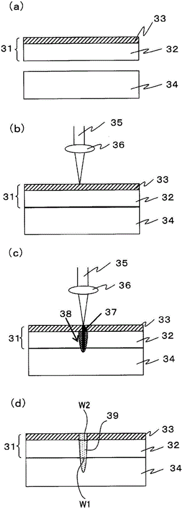
[0126] figure 1 It is a cross-sectional view showing the steps of the laser-bonded component and its manufacturing method according to Embodiment 1 of the present invention.
[0127] Such as figure 1 As shown in (a), the composite sheet 31 is stacked on a copper plate 34 having a thickness of 0.4 mm. A nickel layer 33 with a thickness of 0.1 mm was formed on a copper plate 32 with a thickness of 0.2 mm to form a composite sheet material 31 . The nickel layer 33 is placed on the upper side, and the composite sheet material 31 is superimposed on the desired position on the copper plate 34 . The copper plate 34 corresponds to the metal component X. As shown in FIG. The copper plate 32 corresponds to the metal member Y. As shown in FIG. The nickel layer 33 corresponds to the surface layer. Copper corresponds to the first metal material. Nickel corresponds to the second metal material. A member in which the composite sheet material 31 is stacked on the copper plate 32 corr...
Embodiment approach 2
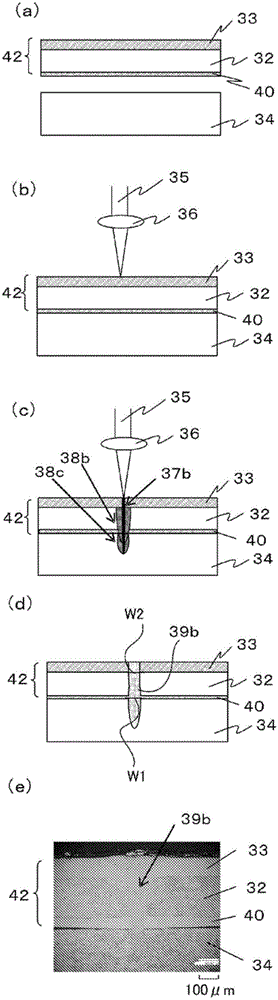
[0139] figure 2 It is a cross-sectional view showing the steps of the laser-bonded component and its manufacturing method according to Embodiment 2 of the present invention. figure 2 (e) is an optical micrograph (halftone image displayed on a monitor) of the cross section of the laser bonding member according to Embodiment 2 including the resolidified portion. exist figure 2 in, for with figure 1 The same symbols are used for the same constituent elements, and their descriptions are omitted.
[0140] exist figure 2 in, with figure 1 The difference is that, as figure 2 As shown in (a), the composite sheet material 31 is replaced with a composite sheet material 42 which has a nickel layer 40 with a thickness of 0.05 mm under the copper sheet 32 (lower surface) in addition to the copper sheet 32 and the nickel layer 33 . The nickel layer 40 corresponds to the intermediate layer.
[0141] exist figure 2 The irradiation sequence of the laser light 35 in (b) and ...
Embodiment approach 3
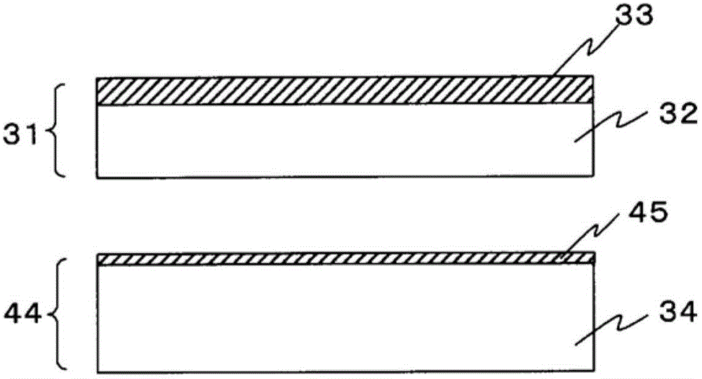
[0145] Figure 4 It is a cross-sectional view showing the steps of the laser-bonded component and its manufacturing method according to Embodiment 3 of the present invention. Figure 4 (c) is an optical micrograph (half-tone image displayed on a monitor) of the cross section of the laser bonding member according to Embodiment 3 including the resolidified portion.
[0146] exist Figure 4 in, with figure 2 The difference is that, as Figure 4 As shown in (a), the condenser lens 36b is installed obliquely so that the laser light 35b can be irradiated obliquely, and Figure 4 In the direction of the paper surface of (a), the surface of the nickel layer 33 is scanned with a laser. As shown in figure (a), the scanning direction is the normal line Ns perpendicular to the surface containing the nickel layer 33, and the irradiation axis A of the laser beam intersecting the normal line Ns. L The direction of the face. In addition, the normal Ns and the illumination axis A inters...
PUM
| Property | Measurement | Unit |
|---|---|---|
| thickness | aaaaa | aaaaa |
| wavelength | aaaaa | aaaaa |
| thickness | aaaaa | aaaaa |
Abstract
Description
Claims
Application Information
 - R&D Engineer
- R&D Manager
- IP Professional
- Industry Leading Data Capabilities
- Powerful AI technology
- Patent DNA Extraction
Browse by: Latest US Patents, China's latest patents, Technical Efficacy Thesaurus, Application Domain, Technology Topic.
© 2024 PatSnap. All rights reserved.Legal|Privacy policy|Modern Slavery Act Transparency Statement|Sitemap