
Method of producing a piezoelectric/electrostrictive device

a piezoelectric/electrostrictive and piezoelectric technology, applied in the direction of device details, instruments, variable capacitors, etc., can solve the problems of reducing affecting the performance of the device, and the difficulty of obtaining a special adhesive that can ensure a sufficient adhesive strength, etc., to achieve a large adhesive strength, reduce and increase the displacement of each movable part.

Inactive Publication Date: 2006-08-15
NGK INSULATORS LTD
View PDF29 Cites 6 Cited by
  • Summary
  • Abstract
  • Description
  • Claims
  • Application Information

AI Technical Summary

Benefits of technology

[0016]Thus, an object of the present invention is to increase the displacement of each movable part and to sufficiently ensure the bonding between each mounting part and the component as well as the fixation of the device itself without changing the total length of the device and without reducing the bonding area at the joining surfaces of the mounting parts in a piezoelectric / electrostrictive device having such a form. Further, an object of the present invention is to firmly mount the component and the device in the case where the component is especially large and heavy or in the case where a large adhesive strength is needed.
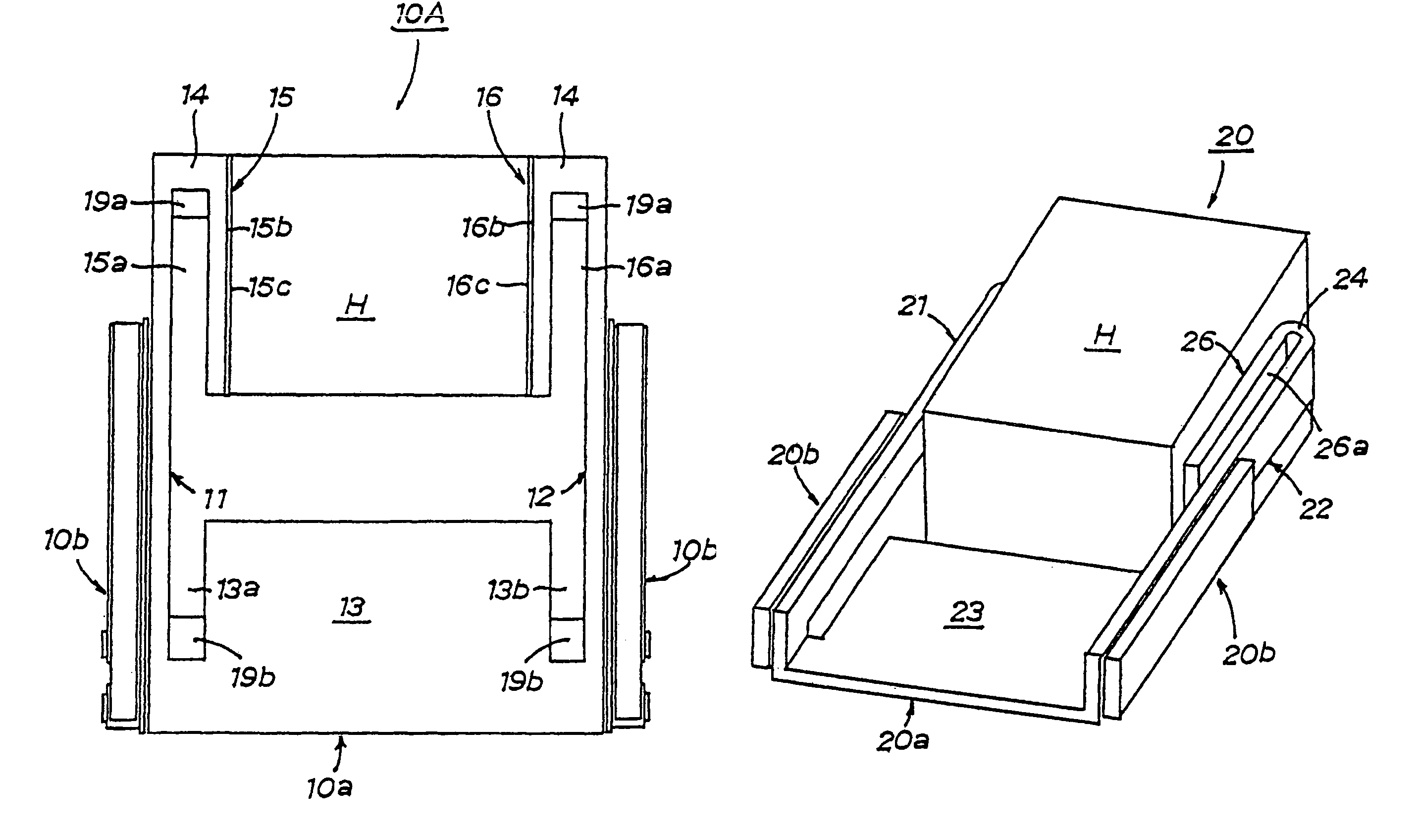
[0028]In the piezoelectric / electrostrictive device according to the present invention, each movable part constituting the base includes a long mounting part, whereby the joining surface of each mounting part is large and the area of bonding the component with each mounting part can be set to be large. For this reason, according to the piezoelectric / electrostrictive device, the adhesive force of the component to the joining surface of each mounting part is strong, so that the component will not be easily dismounted from each mounting part, thereby making it possible to construct a joining structure that is strong against impact. Further, it is possible to prevent a situation in which the separation of the component from one mounting part damages the other mounting part.
[0029]Also, in the joining structure, each mounting part extends for a predetermined length while holding a slit-shaped gap of a predetermined width along the inside surface of each movable part by being turned around at the other end of the movable part. For this reason, a joining structure having a strong adhesive force between each mounting part and the component can be constructed without increasing the total length of the device and without degrading the displacement characteristics of the movable parts.
[0030]Further, according to this joining structure, even if the component to be bonded to the mounting parts is large and has an increased mass to impose a large external force on the adhesive, a large bonding area can be ensured without increasing the total length of the device, so that the distortion per bonding area can be reduced. For this reason, according to the joining structure, the influence given to the device properties by the temperature change of the adhesive can be greatly restrained as compared with the case in which the bonding area is small, and the operation range in which the set device properties are exhibited in a stable state can be extended to a wide range from low temperature to high temperature.
[0031]In the piezoelectric / electrostrictive device according to the present invention, if slit-shaped grooves are provided on both sides of the fixing part constituting the base, the area of the fixing part can be increased, without increasing the total length of the device, by increasing the length of the grooves. By this, the bonding area that fixes the piezoelectric / electrostrictive device can be increased to provide a strong adhesive force, whereby the piezoelectric / electrostrictive device can be firmly fixed. Even if the component to be mounted onto the piezoelectric / electrostrictive device increases in size to have an increased mass and the fixing part must support the combined mass of the device and the component, the adhesive force can be sufficiently enhanced to stabilize the fixation of the device.
[0033]The base can be produced as follows. The first base can be produced with ease by adopting a base block obtained by lamination and calcination of a large number of ceramic green sheets as a material for forming the base, and using means for cutting the base block at a predetermined site along a lamination direction of the ceramic layers to form the base. The second base can be produced with ease by adopting a flexible and bendable flat plate made of metal as a material for forming the base, and stamping the flat plate into a shape that delineates a planar development of the base so as to obtain a stamped structure, and bending the stamped structure at a predetermined site to form the base. The third base can be produced with ease by adopting a flexible and bendable flat plate made of metal and adopting a base block formed by laminating and bonding a large number of the flat plates as a material for forming the base, and using means for cutting the base block at a predetermined site along a lamination direction to form the base.

Problems solved by technology

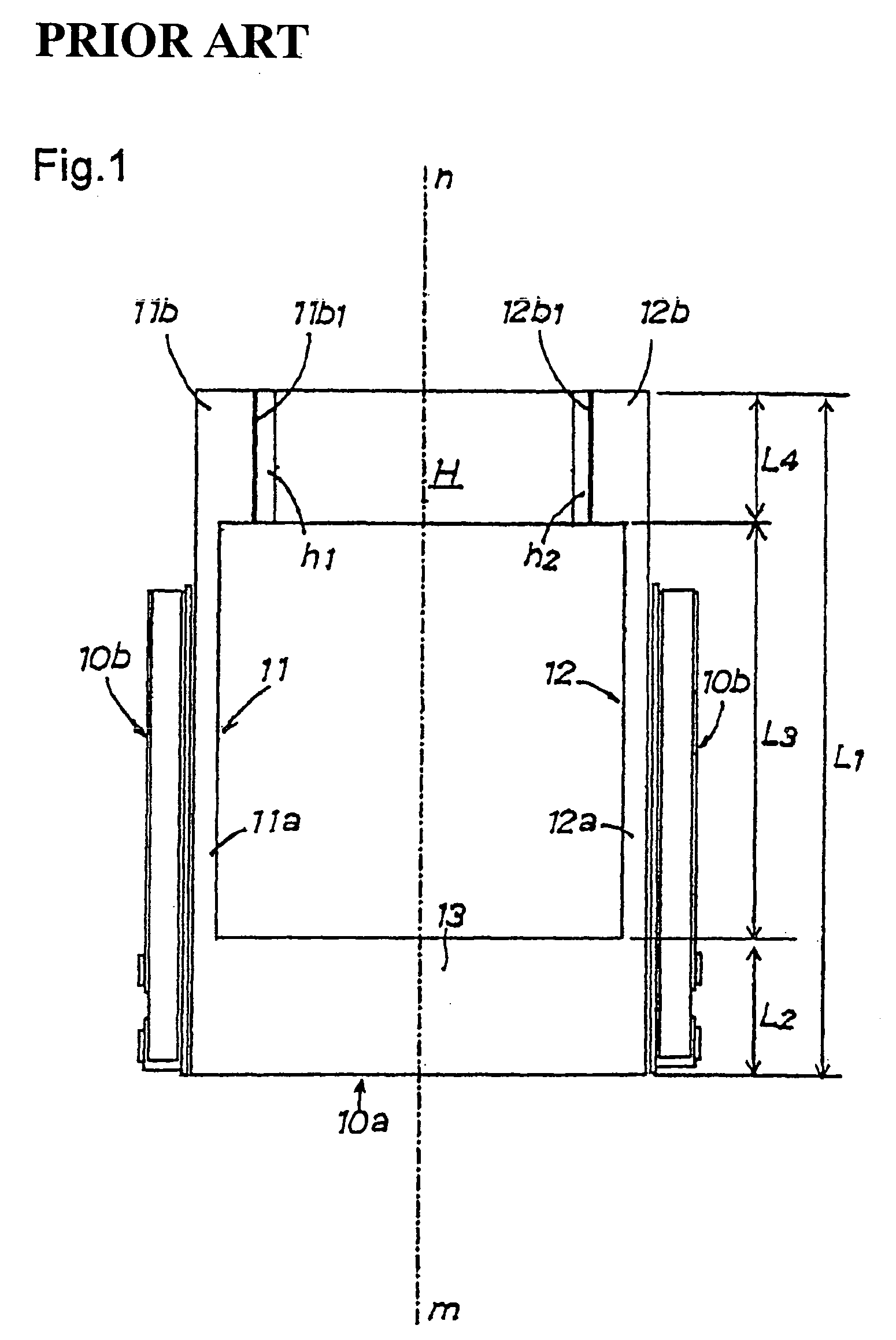
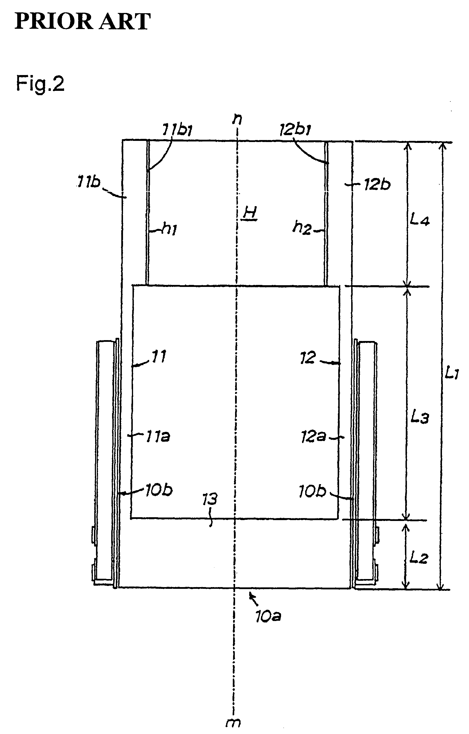
In a piezoelectric / electrostrictive device having such a form, if component H is dismounted from one of mounting parts 11b, 12b, the other of mounting parts 11b, 12b must support component H to succeed receiving the impact applied to component H. In this state, component H is liable to be dismounted from the other mounting part, and also there is a fear that the supporting balance of the mounted state may be lost to cause the one supporting mounting part or the movable part connected thereto to be broken by the action of torsional force.
In order to meet this problem, one must use an adhesive having an extremely high adhesive strength; however, it is generally difficult to obtain a special adhesive that can ensure a sufficient adhesive strength no matter how small the bonding area is.
Furthermore, there is naturally a limit even in the case of using an adhesive having such a special property.

Method used


Image

  • Method of producing a piezoelectric/electrostrictive device
  • Method of producing a piezoelectric/electrostrictive device
  • Method of producing a piezoelectric/electrostrictive device

Examples


example 1

[0127]In this Example, a piezoelectric / electrostrictive device 10 according to the first embodiment of the present invention is prepared, and FIG. 21 shows the dimensional relationship of piezoelectric / electrostrictive device 10 and each site of component H. Symbols L of the same series in piezoelectric / electrostrictive device 10 each denote the length L1 of the device (total length of the base), the length L2 of the fixing part in the base, the length L3 of the arm of the movable parts in the base, the length L4 of the joining surface of the mounting parts in the base, the length L5 of the connecting part, the interval L6 of the slit-shaped gaps between the movable parts and the mounting parts, the interval L7 between the two movable parts, the interval L8 between the two mounting parts, the thickness L9 of the mounting parts, the thickness L10 of the movable parts, the height L11 of the movable parts (the distance in the front-and-back direction of the document sheet), and the len...

example 2

[0136]This Example is a modified example in which the first piezoelectric / electrostrictive device 10 according to the present invention is modified, where a piezoelectric / electrostrictive device 10B is prepared in which the base has a form corresponding to the base of the piezoelectric / electrostrictive device shown in FIG. 15. The dimensional relationship of the sites of piezoelectric / electrostrictive device 10B is shown in FIG. 22. Symbols L of the same series in piezoelectric / electrostrictive device 10B are the same as those in piezoelectric / electrostrictive device 10 formed in Example 1; however, the dimensions of some of the sites and the dimension of the sites of component H are omitted. However, in piezoelectric / electrostrictive device 10B, the width L13 of the slit-shaped gaps in the fixing part and the length L14 of the slit-shaped gaps on the fixing part side, which are not present in piezoelectric / electrostrictive device 10, have been added.

[0137]In piezoelectric / electrost...


PUM

PropertyMeasurementUnit
temperatureaaaaaaaaaa
particle sizeaaaaaaaaaa

Abstract

A method of producing a piezoelectric / electrostrictive device having a base including a pair of movable parts opposing each other, a fixing part that connects the movable parts with each other at one end thereof, and mounting parts that extend for a predetermined length while holding slit-shaped gaps of a predetermined width along inside surfaces of said movable parts by being turned around at the other end of said movable parts, said piezoelectric / electrostrictive device having a piezoelectric / electrostrictive element disposed on at least one outside surface of said movable parts of said base, wherein a base block obtained by laminating and calcining a large number of ceramic green sheets is adopted as a material for forming said base, and the base including said movable parts, said fixing part, and said mounting parts is formed by cutting said base block at a predetermined site along a lamination direction of said ceramic green sheets.

Description

CROSS REFERENCE TO RELATED APPLICATIONS[0001]This application is a division of U.S. application Ser. No. 10 / 237,495 filed Sep. 9, 2002, which in turn is a division of U.S. application Ser. No. 09 / 878,773 filed Jun. 11, 2001, now U.S. Pat. No. 6,531,805, the entireties of which are incorporated herein by reference.BACKGROUND OF THE INVENTION[0002]1. Field of the Invention[0003]The present invention relates to a piezoelectric / electrostrictive device of a form such that the displacement operation of a piezoelectric / electrostrictive element is transmitted to a pair of right and left movable parts to control a component to be controlled, which component is sandwiched and held by the other ends of the movable parts, or the displacement operation of a pair of right and left movable parts that sandwich and hold a component to be inspected on the other end is sensed by a piezoelectric / electrostrictive element to sense the characteristics of the component to be inspected.[0004]2. Description ...

Claims


Application Information

Patent Timeline
Patent Type & Authority Patents(United States)
IPC IPC(8): H04R17/00H01L41/06H10N30/053H10N30/093H10N30/097H10N30/20H10N35/80
CPCG11B5/482G11B5/4873H01L41/43H01L41/273H01L41/0946Y10T29/42Y10T29/49126Y10T29/43Y10T29/435Y10T29/49798G11B5/483H10N30/2043H10N30/053H10N30/097
Inventor IKEDA, KOJITAKAHASHI, FUMITAKESHIBATA, KAZUYOSHI
Owner NGK INSULATORS LTD
Learn More