Electrochromic Display Device

a display device and display technology, applied in static indicating devices, non-linear optics, instruments, etc., can solve the problems of restricting display times, and affecting the reading of displays through these displays

Inactive Publication Date: 2010-06-03
FUNAI ELECTRIC CO LTD
View PDF4 Cites 23 Cited by
  • Summary
  • Abstract
  • Description
  • Claims
  • Application Information

AI Technical Summary

Benefits of technology

[0022]the electrochromic display device displays a selected pixel by applying a voltage of a first potential difference between the first electrode used as a negative electrode and the second electrode used as a positive electrode, the first electrode and the second electrode respectively forming the selected pixel, and applies the voltage...

Problems solved by technology

However, the displays by means of these displays are restricted in places to be read, and are inferior also in the handling aspects of the displays in terms of their weights, sizes, shapes, and portability in comparison with the common displays printed on paper.
Moreover, because these displays consume much electric power, the restriction of display times is also caused in the case of battery drives.
Furthermore, all of these displays is a light emitting type display, and has the problem of causing extreme fatigue at the time of a long hour steady gaze.
However, when the electrochromic display device using the leuco dye is used as the display device of the passive matrix drive, then a sufficient displ...

Method used


Image

  • Electrochromic Display Device
  • Electrochromic Display Device
  • Electrochromic Display Device

Examples


example 1

[0186]In the following, the present invention will be further described in detail by means of a concrete example, but the present invention is not limited to the example.

(Making of Electrochromic Display Device)

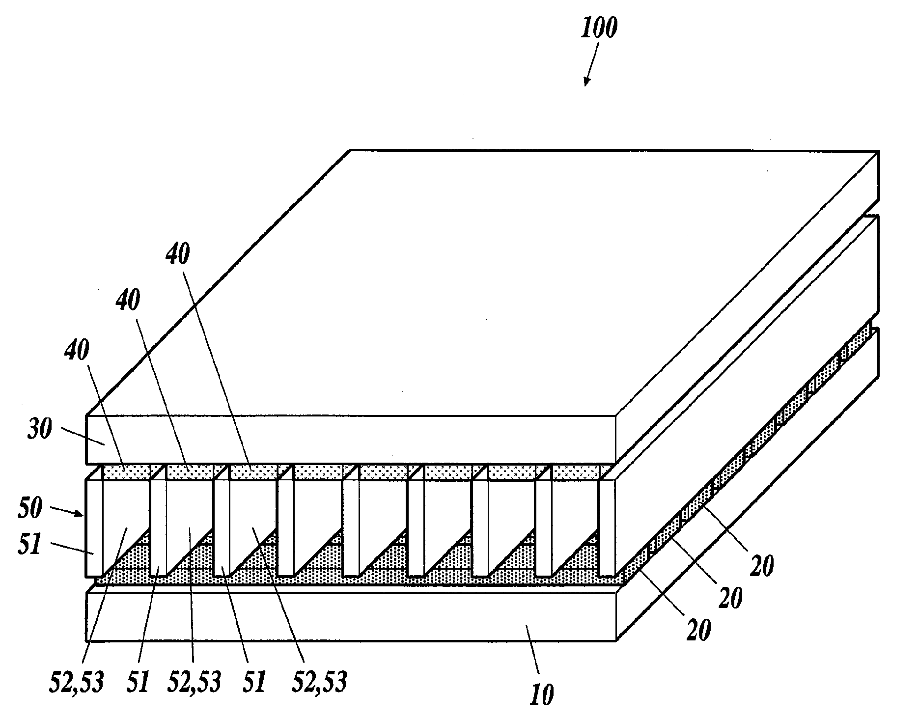
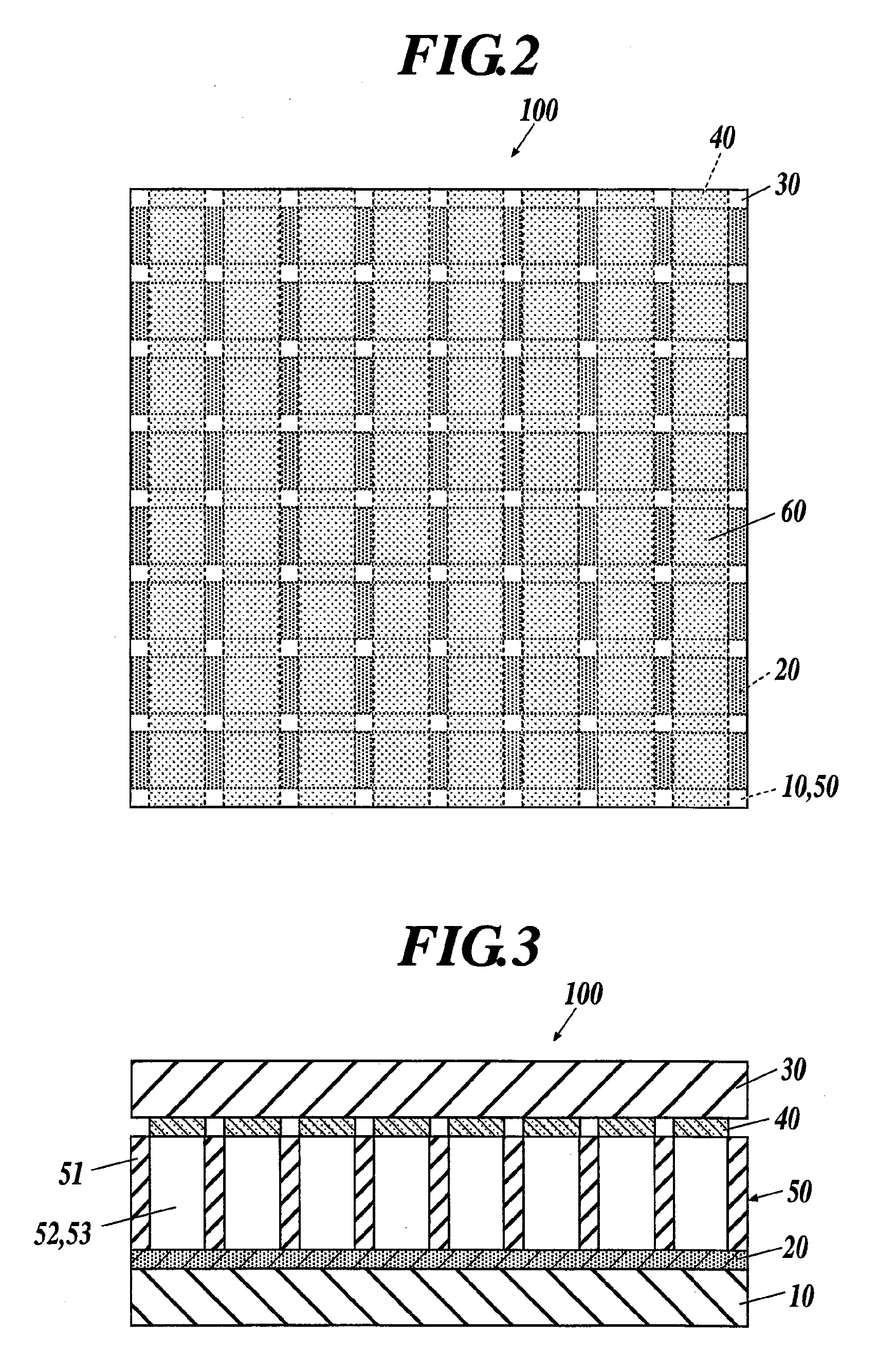
[0187]A rectangular non-alkali glass substrate having a thickness of 0.7 mm was used as the second substrate 30, and an ITO was formed on one surface (the under surface) of the second substrate 30 by sputtering. The sputtered ITO had a film thickness of 200 nm and a surface resistance of 10Ω / □. The ITO formed by the sputtering was patterned into stripes each having a width of 0.42 mm and a pitch of 0.45 mm by the use of the photolithographic method. Thus the second electrodes 40 were made.

[0188]Similarly, a rectangular non-alkali glass substrate was used as the first substrate 10, and chromium was formed on one surface (the upper surface) of the first substrate 10 by sputtering. An oxide film (chromium oxide) was formed on the surface of the sputtered chromium. The sputtered ...

modification 1

(Modification 1)

[0222]The electrochromic display device 100 of the embodiment described above may be provided with adsorption layers 70A containing the adsorbents 53 between the first electrodes 20 and an electrochromic composition layer 50A in place of adding (dispersing) the adsorbents 53 in the electrochromic compositions 52 constituting the electrochromic composition layer 50 as an electrochromic display device 100A shown in, for example, FIGS. 12 and 13.

[0223]The electrochromic composition layer 50A provided in the electrochromic display device 100A of the modification 1 includes the electrochromic compositions 52 to which display quality deterioration inhibitors, polymer compounds, and the like are added, but to which no adsorbents 53 are added.

[0224]Moreover, the electrochromic display device 100A of the modification 1 is provided with the adsorption layers 70A deposited on the first electrodes 20 to contact with the electrochromic composition layer 50A.

[0225]The adsorption l...


PUM


Abstract

Disclosed is an electrochromic display device comprising: a first substrate; a first electrode; a second substrate; a second electrode; and an electrochromic composition layer, wherein the device is of a passive matrix drive where the device performs a display by an energization between the electrodes, and performs a erasion of the display, wherein the first electrode comprises electrodes, the second electrode comprises a plurality of transparent display electrodes, a pixel is formed where the electrodes are in a grade separated crossing, at least a surface of the electrodes is respectively oxidized, the electrochromic composition layer comprising (i) insulative partition walls and (ii) an electrochromic composition including a supporting electrolyte, a polar solvent, and a leuco dye, and wherein the device displays a selected pixel by applying a voltage of a first potential difference, and applies the voltage of a second potential difference so as not to cause any energization.

Description

BACKGROUND OF THE INVENTION[0001]1. Field of the Invention[0002]The present invention relates to an electrochromic display device.[0003]2. Description of Related Art[0004]The publications in the forms of electronic books, that is, electronic publishing, have come to be actively performed in place of the publications by conventional printing techniques as electronic information networks have spread. As the apparatus displaying electronic information to be distributed in these networks, for example, cathode ray tube (CRT) displays and back light type liquid crystal displays have been used. However, the displays by means of these displays are restricted in places to be read, and are inferior also in the handling aspects of the displays in terms of their weights, sizes, shapes, and portability in comparison with the common displays printed on paper. Moreover, because these displays consume much electric power, the restriction of display times is also caused in the case of battery drives...

Claims


Application Information

Patent Timeline
IPC IPC(8): G02F1/153G02F1/163G02F1/1503
CPCG02F1/1521G02F1/155G09G2300/06G02F2001/151G09G3/38G02F1/163G02F2001/1518G02F1/1503
Inventor HIGUCHI, TETSUYASUZUKI, MASAOFUKUOKA, TOSHIMIWENG, WU
Owner FUNAI ELECTRIC CO LTD
Why Eureka
Try Eureka