
Flat non-aqueous electrolyte secondary cell

a non-aqueous electrolyte, secondary cell technology, applied in the direction of non-aqueous electrolyte cells, wound/folded electrode electrodes, sustainable manufacturing/processing, etc., can solve the problem of limiting the miniaturization of these cells at present, inconvenient use, and inability to meet the needs of large-scale production and use, so as to achieve the effect of significantly improving the discharge characteristics of the heavy-loading secondary cell

Inactive Publication Date: 2005-12-08
MAXELL HLDG LTD
View PDF7 Cites 24 Cited by
  • Summary
  • Abstract
  • Description
  • Claims
  • Application Information

AI Technical Summary

Benefits of technology

[0011] The present inventors made extensive study on the improvement of the heavy-loading discharge characteristics of the flat non-aqueous electrolyte secondary cell described above. As a result, they found that the heavy-loading discharge characteristics are significantly improved by allowing the area of the electrodes to be significantly larger than in the conventional flat non-aqueous electrolyte secondary cell, to arrive at the present invention.
[0015] As described above, the total sum of the areas of the opposing cathodes and anodes in the electrode group is made larger than the area of the opening of the insulating gasket or the opening-sealed plate, whereby the heavy-loading discharge characteristics of the flat non-aqueous electrolyte secondary cell can be significantly improved.

Problems solved by technology

However, these cells have been constructed in such a complicated process that they are inferior in workability and the miniaturization of parts therein is also difficult.
Further, these cells should be provided therein with a space for preventing the tab terminal from short-circuiting or for integrating a large number of parts such as safety element into the cells, and thus there is a limit to the miniaturization of these cells at present.
However, this cell though attaining superior characteristics to the conventional flat non-aqueous electrolyte secondary cell is not satisfactory when discharged in a large current required of a main power source in compact portable devices, thus failing to achieve levels satisfactory as a main power source in compact portable devices.

Method used


Image

  • Flat non-aqueous electrolyte secondary cell
  • Flat non-aqueous electrolyte secondary cell
  • Flat non-aqueous electrolyte secondary cell

Examples


example 1

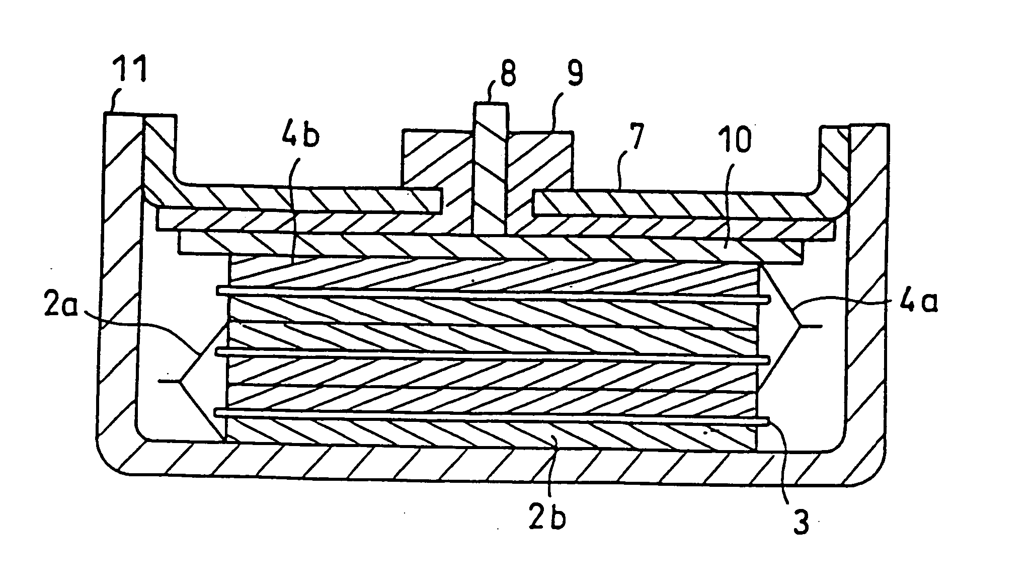
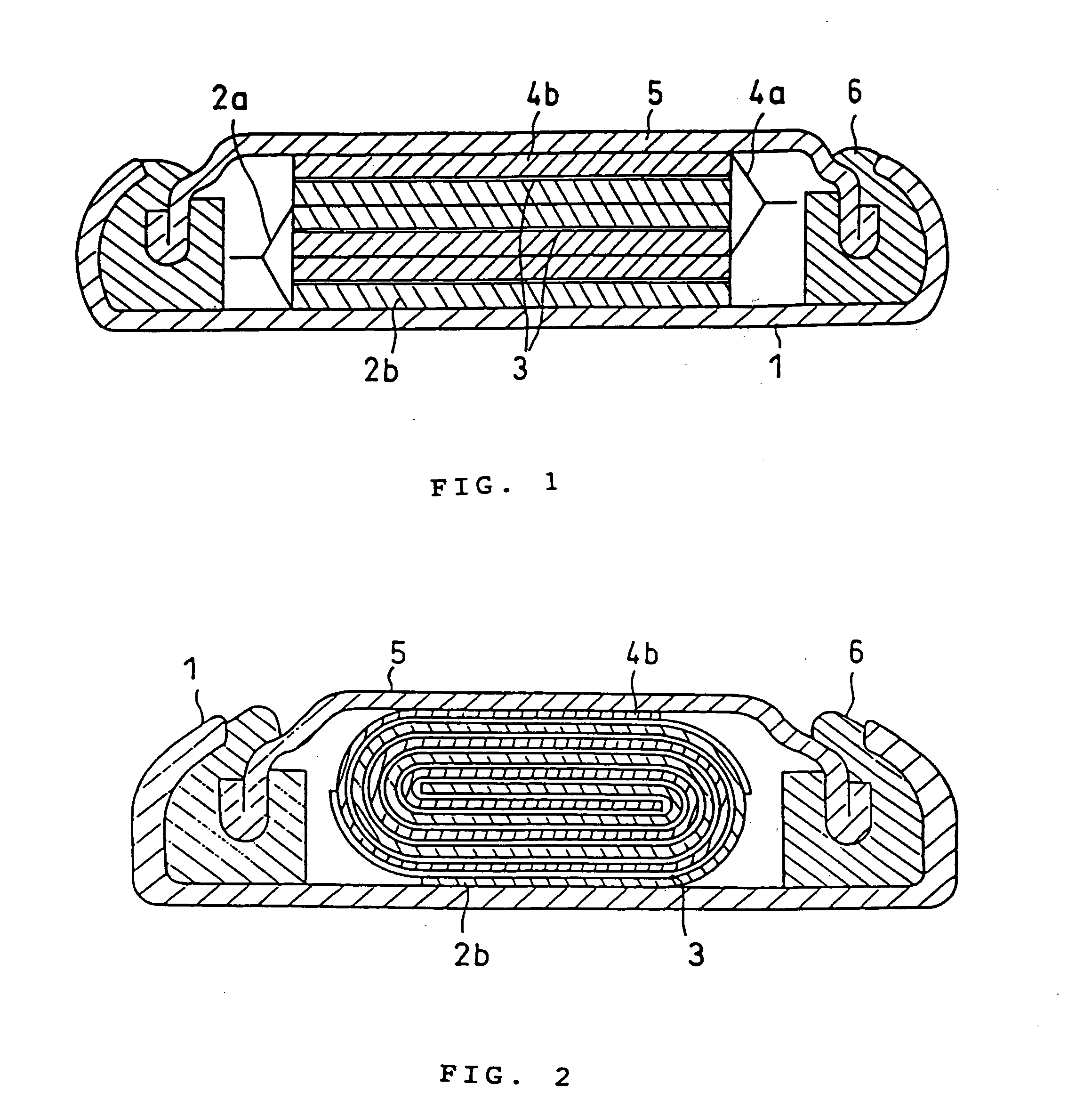
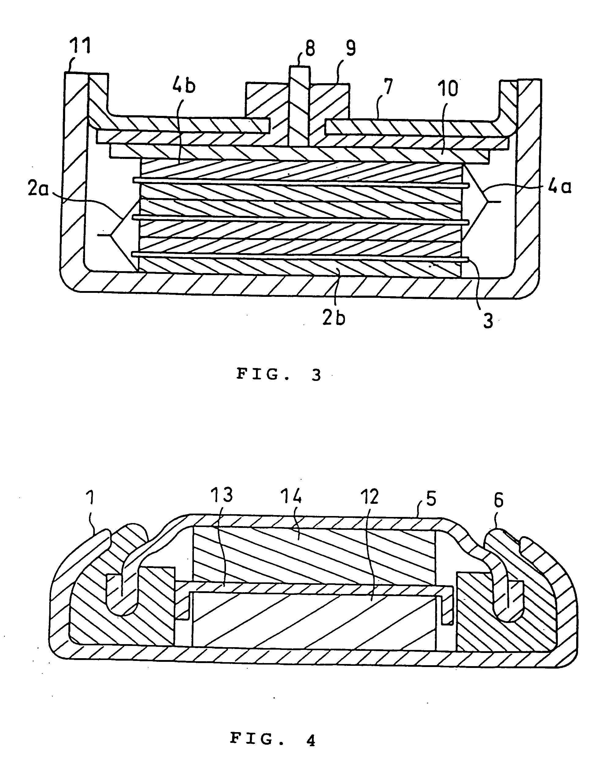
[0060] A process for producing the cell of the present invention in Example 1 is described by reference to the sectional drawing in FIG. 1.

[0061] First, 5 parts by weight of acetylene black and 5 parts by weight of graphite powder were added as electrically conductive agents to 100 parts by weight of LiCoO2, and 5 parts by weight of polyvinylidene fluoride was added as a binding agent, and these materials were diluted with N-methyl pyrrolidone and mixed to give a cathode mix for cell in a slurry form. Then, this cathode mix was applied with a doctor blade onto one side of an aluminum foil of 0.02 mm in thickness as a cathode current-collecting body 2a, followed by drying it. This procedure of application and drying was repeatedly conducted until the thickness of the resulting coating of the active material-containing layer reached 0.39 mm, whereby the cathode active material-containing layer 2b was formed on one side of the aluminum foil to prepare a single-coated cathode.

[0062] T...

example 2

[0068] A cell was constructed in the same manner as in Example 1 except that the coating of the active material-containing layer in each of the cathode and anode in the electrode group was 0.22 mm in thickness on one side, and the number of double-coated cathodes or double-coated anodes laminated internally in the electrode group was 2. The number of faces where a cathode was opposite an anode via a separator is 5 in total, and the total sum of the areas of the opposing cathodes and anodes is 8.5 cm2.

example 3

[0069] A cell was constructed in the same manner as in Example 1 except that the coating of the active material-containing layer in each of the cathode and anode in the electrode group was 0.15 mm in thickness on one side, and the number of double-coated cathodes or double-coated anodes laminated internally in the electrode group was 3. The number of faces where a cathode was opposite an anode via a separator is 7 in total, and the total sum of the areas of the opposing cathodes and anodes is 11.8 cm2.


PUM


Abstract

In a flat non-aqueous electrolyte secondary cell comprising an electricity-generating element including at least a cathode, a separator and an anode and a non-aqueous electrolyte in the inside of a cathode case, a plurality of electrode units each consisting of the cathode and the anode opposite to each another via the separator are laminated to form an electrode group, or an electrode unit in a sheet form consisting of the cathode and the anode opposite to each another via the separator is wound to form an electrode group, or a sheet-shape cathode is wrapped with the separator except for a part contacting at inner face of cathode case and a sheet-shaped anode is set on the sheet-shaped cathode in a right angled position each other and then these cathode and anode are bent alternately to form an electrode group, and the total sum of the areas of the opposing cathode and anode in this electrode group is larger than the area of the opening of an insulating gasket in a sealed portion in the cathode case or than the area of an opening in a sealed plate in a sealed portion in the cathode case, whereby the discharge capacity upon heavy-loading discharge is significantly increased as compared with the conventional cells. Accordingly, while the size of the cell is small, the discharge capacity is increased as described above, and thus it is possible to provide a highly utilizable flat non-aqueous electrolyte secondary cell. Further, in said flat non-aqueous electrolyte secondary cell, problems which may be caused by the increased discharge capacity in the cell can be solved by improving the solvent and supporting electrolyte for the electrolyte or by various improvements in the cathode and anode cases.

Description

BACKGROUND OF THE INVENTION [0001] 1. Field of the Invention [0002] The present invention relates to a flat non-aqueous electrolyte secondary cell and in particular to a flat non-aqueous electrolyte secondary cell with improvements in heavy loading discharge characteristics. [0003] 2. Description of the Prior Art [0004] In recent years, there are commercially available coin- or button-shaped flat non-aqueous electrolyte secondary cells wherein metal oxides such as MnO2 and V2O5, inorganic compounds such as fluorinated graphite, or organic compounds such as polyaniline and polyacene structural compounds are used as the cathode active material, while metal lithium or lithium alloys, organic compounds such as polyacene structural compounds, carbon materials capable of occluding and releasing lithium, or oxides such as lithium titanate or lithium-containing silicon oxides are used in the anode, and non-aqueous electrolytes containing a supporting electrolyte such as LiClO4, LiPF6, LiBF4...

Claims


Application Information

Patent Timeline
IPC IPC(8): H01M4/02H01M4/13H01M4/58H01M4/587H01M4/66H01M6/10H01M6/16H01M10/04H01M10/052H01M10/0525H01M10/0568H01M10/0569H01M10/0583H01M10/0585H01M10/0587H01M10/36H01M50/119H01M50/133
CPCH01M2/0222H01M2/027H01M2/0275H01M2/1241H01M4/13H01M4/587H01M4/669H01M6/10H01M6/103H01M6/164H01M10/0427H01M10/0431H01M10/052H01M10/0525H01M10/0568H01M10/0569H01M10/0583H01M10/0585H01M10/0587H01M2004/021H01M2006/106Y02E60/10H01M50/109H01M50/545H01M50/3425Y02P70/50H01M50/133H01M50/119
Inventor SUZUKI, MASAMIHAYAMI, MUNETOUDAGAWA, KAZUOIIZUKA, KAZUOISHIHARA, NAOMIHIRAHARA, SATOSHISAKAI, HIROTAKAYODA, KIYOTOSHIKOTA, MASATAKA
Owner MAXELL HLDG LTD
Learn More