Method of producing solid electrolytic capacitor

a solid electrolytic capacitor and electrolytic capacitor technology, applied in the manufacture of electrolytic capacitors, capacitors, electrolytes/absorbents, etc., can solve the problems of inability to overcome, the simple transfer of tantalum electrolytic capacitors' conventional technology is far from manufacturing practically applicable ones, and the leakage current is likely to increase. , to achieve the effect of reducing the leakage current and high capacitance occurrence ra

Inactive Publication Date: 2006-10-24
SAN DENSHI INDS
View PDF4 Cites 23 Cited by
  • Summary
  • Abstract
  • Description
  • Claims
  • Application Information

AI Technical Summary

Benefits of technology

[0017]The present invention provides a niobium anode / conductive polymer cathode capacitor that is high in the capacitance occurrence rate and can sufficiently reduce the leakage current owing to the aging.
[0021]According to the manufacturing method according to the invention, an excellent quality conductive polymer layer can be assuredly formed to a center portion of a niobium anode body on which a dielectrics film layer is formed; accordingly, a solid electrolytic capacitor in which the capacitance occurrence rate is high and the leakage current can be sufficiently reduced by means of the aging can be provided.
[0022]In the case of a niobium sintered element being used as the anode body, so far it was very difficult to form the chemically polymerized conductive polymer layer to the center portion of the element; furthermore, even when the electrolytically polymerized conductive polymer layer is formed thereon, the electrolytically polymerized conductive polymer layer cannot be formed to the center portion of the element. Accordingly, the capacitance occurrence rate as a capacitor is low and the aging is applied with difficulty. However, according to the invention, the chemically polymerized conductive polymer layer can be formed sufficiently to the center portion of the element. As a result, the electrolytically polymerized conductive polymer layer that is formed thereon, even when a range of condition selection concerning materials and formation methods is expanded, can be formed sufficiently to the center portion of the element.
[0024]To the solution of oxidizing agent that is used in the step of forming the first conductive polymer layer, in order to lower the surface tension of the solution, a water-soluble organic solvent such as alcohols and so on may be added.

Problems solved by technology

However, there are many problems in that in an electrolytic capacitor that uses niobium as the anode material, the leakage current is likely to increase, the aging treatment (an operation to make defect portions of a dielectrics film insulative by applying a direct current voltage in accordance with the polarity of the capacitor for a long period of time) to reduce the leakage current is difficult to demonstrate desired effects, a value of electrostatic capacitance is likely to fluctuate according to a direct current bias voltage and so on.
These problems cannot be overcome by simply applying the technologies that are used in the tantalum anode body.
However, as the researches of the niobium electrolytic capacitors progress as mentioned above, the differences from the case where the tantalum anode body is used are gradually revealed, and it has become obvious that simple transfer of the conventional technology of the tantalum electrolytic capacitors is far from manufacturing practically applicable ones.
Firstly, when a dielectrics film layer and a conductive polymer cathode layer are formed on a surface of a anode element that is made of a niobium sintered body, even when the conditions the same as that in the case where a tantalum sintered element is used are applied to form the respective layers, the leakage current becomes very large, that is, an almost short-circuited state is caused, resulting in being incapable of, in many cases, carrying out the aging treatment.
That is, different from the case where the tantalum sintered body is used, it is very difficult to form the conductive polymer layer to a center portion of the niobium sintered body.
On the other hand, in the case where the niobium sintered body is used, it is not easy to conquer a wall of from 20 to 30%.

Method used


Image

  • Method of producing solid electrolytic capacitor
  • Method of producing solid electrolytic capacitor
  • Method of producing solid electrolytic capacitor

Examples


reference example 2

[0077]Except that in the step of forming the first conductive polymer layer an oxidant solution in which 2.3% or 10% by weight of ammonium persulfate and 2.8% by weight of disodium m-benzenesulfonate were dissolved in water was used, under the conditions the same as that of embodiment 1, 2 kinds of capacitors were prepared.

[0078]The electrical characteristics of the capacitors are shown in Table 5.

[0079]

TABLE 5ConcentrationCapac-of ammoniumElectrostaticitancepersulfatecapacitanceoccurrenceESRLC(% by weight)(μF)rate (%)(mΩ)(μA)Reference2.3768450embodiment 2aReference1014127330embodiment 2b

[0080]Thus, even when the first conductive polymer layer is formed of chemically polymerized polypyrrole, when the formation conditions thereof (components of the oxidant solution in this case) deviate from the technical range of the invention, though the aging can be applied and the leakage current can be reduced, the practically applicable level of the capacitance occurrence rate cannot be obtaine...

reference example 3

[0081]Except that in the step of forming the first conductive polymer, a solution in which 10 g of 3, 4-ethylenedioxythiophene and 16 g of ferric para-toluene sulfonate were dissolved in 74 g of isopropanol was cooled to 5 degree centigrade, a anode element thereon a dielectrics film layer was formed was immersed in the solution followed, after pulling up, by leaving at 25 degree centigrade for 1 hr, and thereby a chemically polymerized polythiophene derivative layer as the first conductive polymer layer was formed, under the conditions the same as that of embodiment 1, a capacitor was prepared.

[0082]The electrostatic capacitance of the capacitor was 85 μF (capacitance occurrence rate: 76%) and the ESR was 75 mΩ; however, as to the leakage current, since it was in an almost short-circuited state, the aging could not be applied.

[0083]Thus, when the first conductive polymer layer is formed of a chemically polymerized polythiophene derivative, though a practically applicable level of t...

reference example 4

[0084]Except that in the step of forming the first conductive polymer layer, under the conditions the same as that in reference embodiment 3, the operation of forming the chemically polymerized polythiophene derivative layer was repeated ten times and the operation for forming the second conductive polymer layer was not carried out, under the conditions the same as that in embodiment 1, a capacitor was prepared.

[0085]The electrostatic capacitance of the capacitor was 50 μF (capacitance occurrence rate: 45%) and the ESR was 800 mΩ; however, as to the leakage current, since it was in an almost short-circuited state, the aging could not be applied.

[0086]Similarly to the case of reference embodiment 3, when a conductive polymer layer that is formed immediately above the dielectrics film layer is formed of a chemically polymerized polythiophene derivative, in view of the aging, it cannot be put into practical use.


PUM

PropertyMeasurementUnit
electrostatic capacitanceaaaaaaaaaa

Abstract

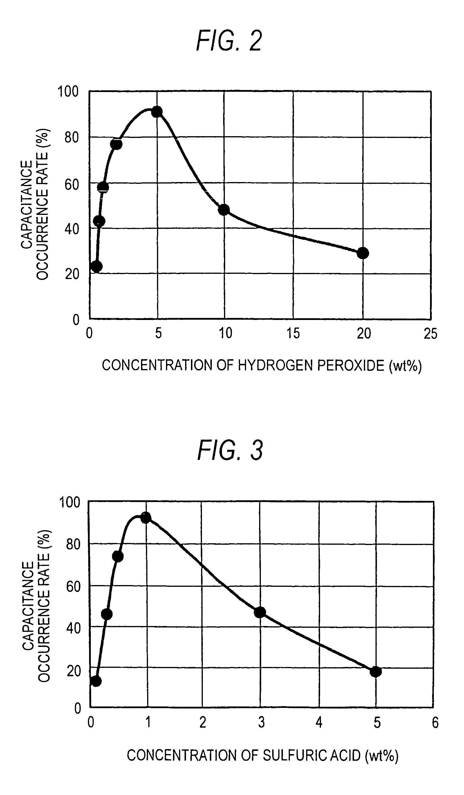
A manufacturing method according to the present invention of a solid electrolytic capacitor includes: a step of immersing a anode body on which the dielectrics film layer is formed in a solution that includes from 0.7 to 10% by weight of hydrogen peroxide, from 0.3 to 3% by weight of sulfuric acid and water as a main solvent, followed by, after pulling up, exposing to vapor of pyrrole or a pyrrole derivative, and thereby forming, on the dielectrics film layer, a first conductive polymer layer made of polypyrrole or a polypyrrole derivative; and a step of immersing the anode body on which the dielectrics film layer and the first conductive polymer layer are formed in a solution that includes a polymerizing monomer and a supporting electrolyte to electrolytically polymerize the polymerizing monomer, and thereby forming a second conductive polymer layer on the first conductive polymer layer.

Description

[0001]This application is the U.S. national phase of international application PCT / JP02 / 08231 filed 14 Aug. 2002, which designated the U.S. PCT / JP2 / 08231 claims priority to JP Application No. 2001-249210 filed 20 Aug. 2001. The entire contents of these applications are incorporated herein by reference.TECHNICAL FIELD[0002]The present invention relates to a solid electrolytic capacitor that employs niobium or an alloy mainly made of niobium as a anode material and a conductive polymer as a cathode material.BACKGROUND ART[0003]As a anode body of an electrolytic capacitor, a wound body of surface-roughened aluminum foil, a single layer body or multi-layered body of surface-roughened aluminum thin plate, a porous sintered body of tantalum powder and so on are much used.[0004]As a material of the anode body, niobium is also gathering attention.[0005]Niobium that, similarly to tantalum, belongs to 5A group in the periodic table is a metal close in the physical properties to tantalum and h...

Claims


Application Information

Patent Timeline
Patent Type & Authority Patents(United States)
IPC IPC(8): H01L21/8249H01G9/028H01G9/00H01G9/02
CPCH01G9/0036H01G9/028
Inventor TAKETANI, YUTAKAHASABA, YOSHIAKISAKAMAKI, MAKOTOITO, TADAHITO
Owner SAN DENSHI INDS
Why Eureka
Try Eureka