Downhole Timing Recovery and Signal Detection

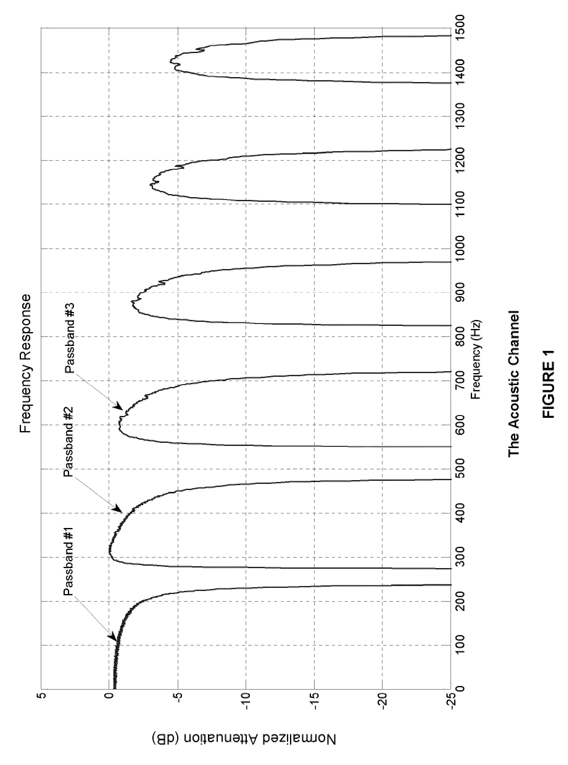
a timing recovery and signal detection technology, applied in the field of telemetry apparatus and methods, can solve the problems of narrow passbands with attenuations of 10 db or greater, frequency dependent destructive interference of signals within these passbands, and limited frequency bandwidth of acoustic signals transmitted up the drillpipe to the surface, so as to improve the detection and synchronization of acoustic signals and increase the operating baud rate

Inactive Publication Date: 2010-06-03
BAKER HUGHES OILFIELD OPERATIONS LLC
View PDF4 Cites 11 Cited by
  • Summary
  • Abstract
  • Description
  • Claims
  • Application Information

AI Technical Summary

Benefits of technology

[0016]In accordance with the invention, a method that improves the detection and synchronization of an acoustic signal and that increases the operating baud rate by modifying the time-bandwidth product of the transmitted linear acoustic chirp at the receiver is provided.
[0020]In another embodiment, an autocorrelation function of the received signal is calculated and the autocorrelation function is optimized to compensate for limited chirp bandwidth. In another embodiment, the autocorrelation function is optimized to remove dispersion effects.

Problems solved by technology

Further still, other factors including significant surface and downhole noise from drilling, dispersion, phase non-linearity and frequency dependent attenuation as well as passband effects all contribute to the challenge of effectively enabling acoustic telemetry through the drillpipe.
Thus, as a result of the passband / stopband structure, the acoustic signal transmitted up the drillpipe to the surface must be limited in frequency bandwidth such that its frequencies fall within one or simultaneously two or more of the frequency passbands within the passband / stopband structure.
However, the main challenge in effective transmission up the drillpipe is the frequency dependant destructive interference of the signals within these passbands.
This interference arises from both the effect of the regular structure of the drill string (Drumheller), and signal reflections local to the acoustic transmitter.
The combination of the fine structure of the passband with the destructive interference of the transmitted signal by local reflections can result in narrow notches within the passband with attenuations of 10 dB or greater.
The bandpass filter properties of the downhole acoustic channel limit the frequency span available for the chirp placing a limit on the time bandwidth product.
This combination of constraints forms a boundary on the available performance of the acoustic telemetry system by limiting the shape of the auto-correlation waveform, making it more difficult to demodulate and detect the telemetry signal at higher data rates.

Method used


Image

  • Downhole Timing Recovery and Signal Detection
  • Downhole Timing Recovery and Signal Detection
  • Downhole Timing Recovery and Signal Detection

Examples


Embodiment Construction

Overview

[0033]With reference to the figures, systems and methods of improved acoustic telemetry are described.

[0034]As noted above, the unique transmission characteristics of the down-hole environment within the available acoustic channels of a typical drill pipe string create an extremely difficult digital communications environment given that the frequency channel is a narrow, highly dispersive band-pass system with substantial levels of echoes, reverberation and attenuation.

[0035]As noted above, one digital communication scheme that has been used with success in this environment is a BPSK or PSK signal modulated on a linear chirp that is centered on one of the passbands of the channel. A working system using this approach is described in detail by Camwell and Neff in “Field Test Results of an Acoustic MWD System”.

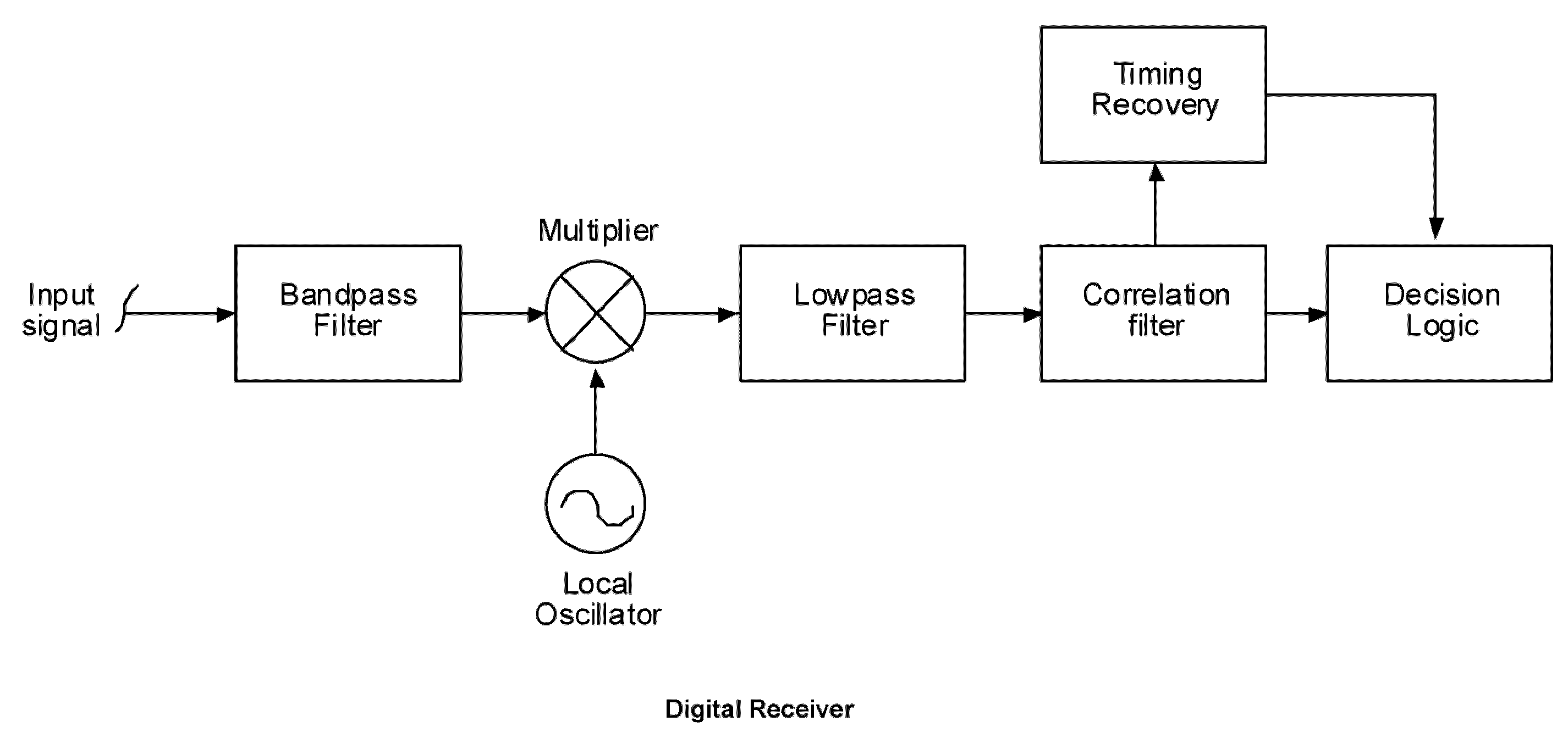
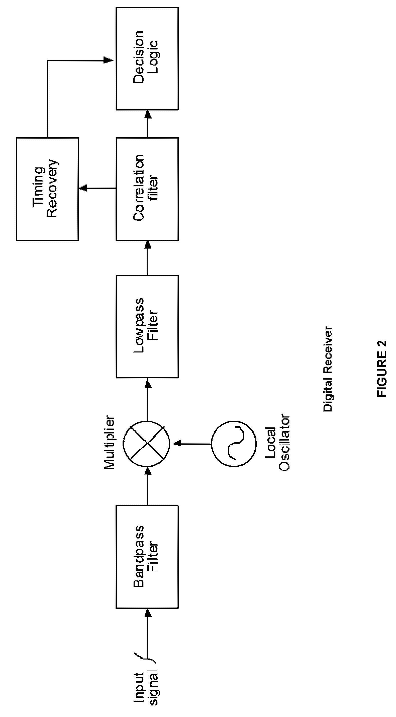
[0036]The receiver in this system employs a correlation demodulator as described by Proakis pp: 234-238. In this case the demodulator correlates the received data stream...


PUM


Abstract

The present invention relates to telemetry apparatus and methods, and more particularly to acoustic telemetry apparatus and methods used in the oil and gas industry. More specifically, the invention relates to a method for enhancing a received signal transmitted by acoustic telemetry through a drill string by modifying the received signal by a multiplication of the received signal with a second waveform.

Description

RELATED APPLICATIONS[0001]This application is related to and claims priority from U.S. Provisional Patent Application No. 61 / 118,501, filed Nov. 28, 2008, the entire contents of which are incorporated herein by reference for all purposes.FIELD OF THE INVENTION[0002]The present invention relates to telemetry apparatus and methods, and more particularly to acoustic telemetry apparatus and methods used in the oil and gas industry. More specifically, the invention relates to a method for enhancing a received signal transmitted by acoustic telemetry through a drill string by modifying the received signal by a multiplication of the received signal with a second waveform.BACKGROUND OF THE INVENTION[0003]As is known, acoustic telemetry is a method of communication in the well drilling and production industry. In a typical drilling environment, acoustic carrier waves from a downhole acoustic telemetry device are modulated in order to carry information via the drillpipe to the surface. Upon a...

Claims


Application Information

Patent Timeline
Patent Type & Authority Applications(United States)
IPC IPC(8): E21B47/16
CPCE21B47/16
Inventor MCRORY, JOHN G
Owner BAKER HUGHES OILFIELD OPERATIONS LLC
Why Eureka
Try Eureka