Cell temperature sensing apparatus for a batttery module

a cell temperature sensing and battery module technology, applied in the field of battery modules, can solve the problems of manufacturing difficulties, difficulty in accurately and reliably placing the thermistors in high-volume manufacturing processes,

Active Publication Date: 2010-06-03
DELPHI TECH IP LTD
View PDF32 Cites 77 Cited by
  • Summary
  • Abstract
  • Description
  • Claims
  • Application Information

AI Technical Summary

Benefits of technology

[0003]The present invention is directed to a battery module having an improved thermistor mounting apparatus for sensing battery cell temperatures. A printed circuit board mounted on the battery module over the battery cells is provided with an array of openings in alignment with selected battery cells for receiving temperature-sensing units that electrically couple with conductor pads formed on the printed circuit board and resiliently engage the selected battery cells. Each such temperature-sensing unit includes a printed circuit board mountable lamp socket, and a lamp socket insert including a thermistor in thermal proximity to a respective battery cell and a compressible support element that resiliently maintains the thermistor in thermal proximity to the battery cell when the sensor unit is installed in a respective printed circuit board opening. In a first embodiment, the insert is seated in a neo-wedge-base lamp socket, and comprises a radial leaded thermistor and a compressible sleeve that resiliently supports the thermistor element relative to the lamp socket. In a second embodiment, the insert is seated in a wedge-base lamp socket, and comprises a surface-mount thermistor attached to a flexible circuit that is over-molded with a compressible moldable material such as silicone rubber.

Problems solved by technology

The temperature of a battery cell can be adequately measured with a thermistor that is in contact with the case of the battery cell, particularly with a metal-case battery cell, but it is difficult to accurately and reliably place the thermistors in high-volume manufacturing processes.
And there are further manufacturing difficulties associated with handling and routing the thermistor leads.

Method used


Image

  • Cell temperature sensing apparatus for a batttery module
  • Cell temperature sensing apparatus for a batttery module
  • Cell temperature sensing apparatus for a batttery module

Examples


Embodiment Construction

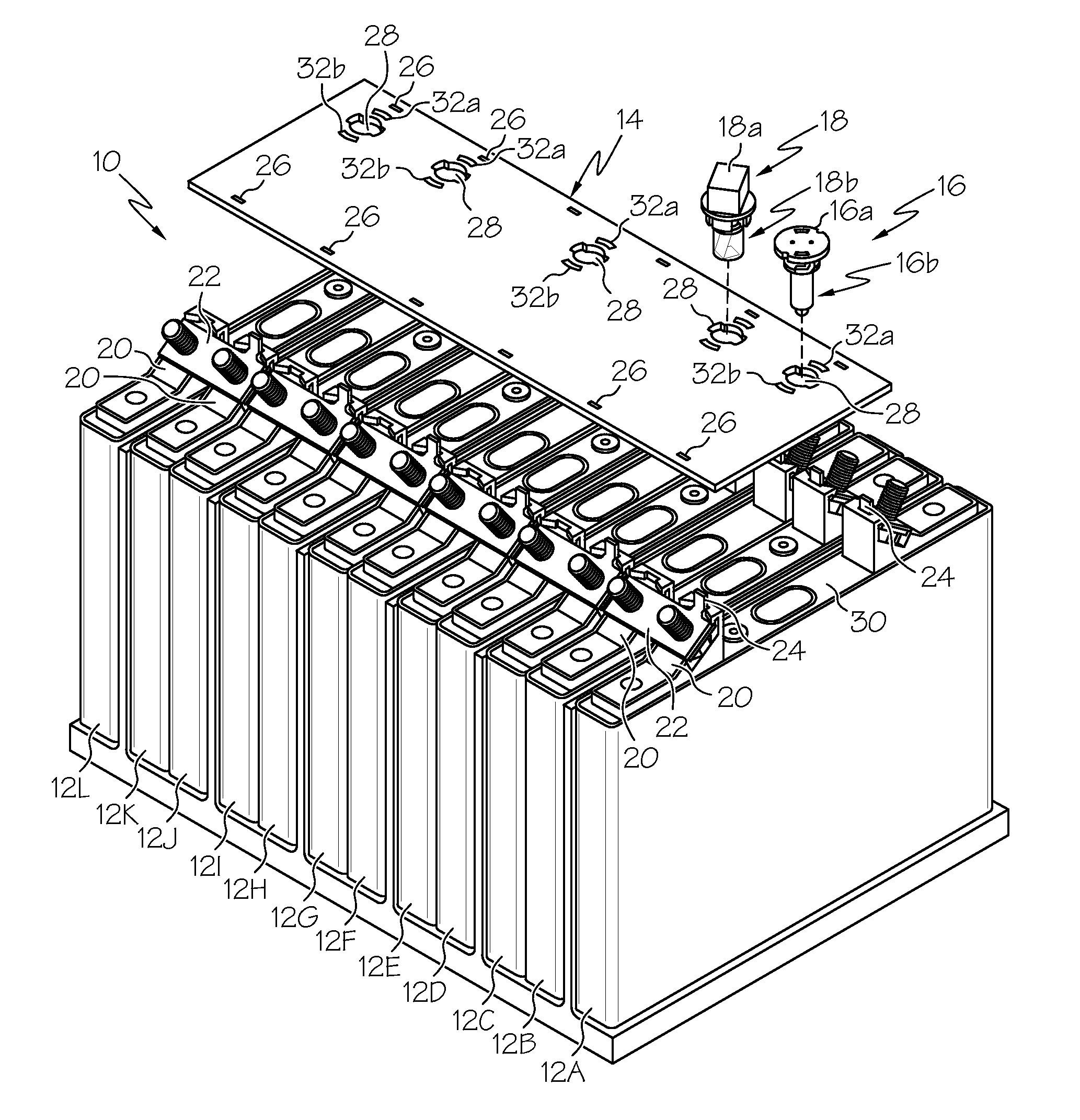
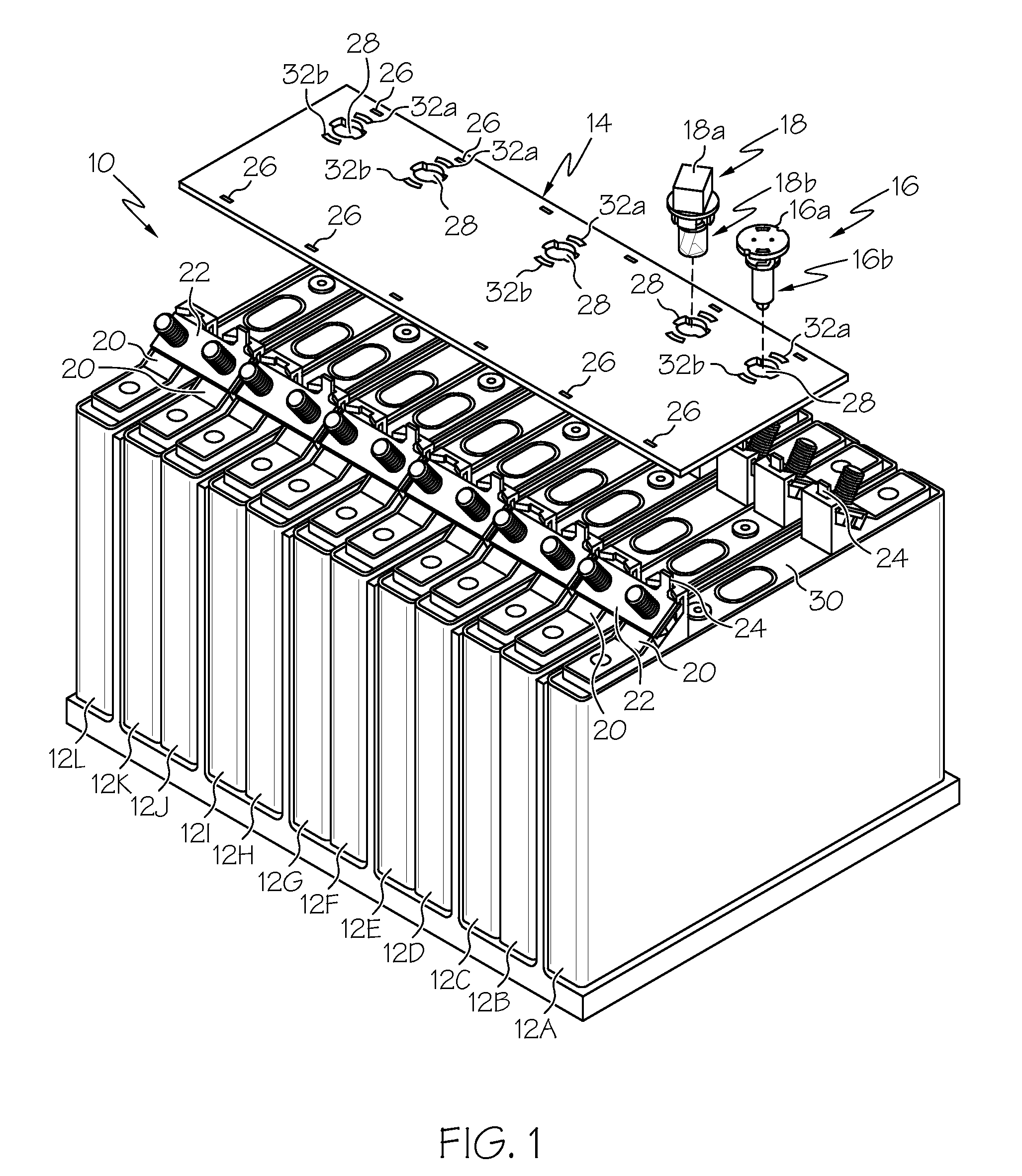
[0008]Referring to the drawings, and particularly to FIG. 1, the reference numeral 10 generally designates a multi-cell lithium-ion battery module for high-power automotive or other applications. In the illustrated embodiment, the module 10 comprises twelve co-packaged battery cells 12A, 12B, 12C, 12D, 12E, 12F, 12G, 12H, 12I, 12J, 12K, 12L, a planar printed circuit board 14, and first and second temperature-sensing units 16 and 18.

[0009]The battery cells 12A-12L of the module 10 are provided with oppositely disposed terminals 20 that are connected in a series chain by sets of bus-bars 22 located on either side of the module 10. Each terminal 20 includes an integral vertically extending tab 24, and the circuit board 14 is provided with a set of corresponding plated through-holes 26 that receive the terminal tabs 24. In this way, the terminal tabs 24 support the circuit board 14 over the battery cells 12A-12L, in addition to providing cell voltage sensing nodes at each of the through...


PUM

PropertyMeasurementUnit
temperatureaaaaaaaaaa
compressibleaaaaaaaaaa
shapeaaaaaaaaaa

Abstract

A printed circuit board supported over the top surface of a multi-cell battery module for battery cell voltage and temperature monitoring has an array of openings in alignment with selected battery cells for receiving temperature-sensing units that electrically couple with contacts formed on the printed circuit board and resiliently engage the cases of the selected battery cells. Each such temperature-sensing unit includes a printed circuit board mountable lamp socket and a lamp socket insert including a thermistor and a compressible element that maintains the thermistor in thermal proximity to the battery cell case when the temperature-sensing unit is installed in a respective printed circuit board opening.

Description

TECHNICAL FIELD[0001]The present invention relates to battery modules that require cell temperature monitoring, and more particularly to a battery module with a novel temperature sensing apparatus.BACKGROUND OF THE INVENTION[0002]High power battery modules comprising a number of co-packaged and interconnected lithium-ion or other battery cells frequently require individual cell temperature monitoring to optimize battery module life and prevent temperature-related failures. The temperature of a battery cell can be adequately measured with a thermistor that is in contact with the case of the battery cell, particularly with a metal-case battery cell, but it is difficult to accurately and reliably place the thermistors in high-volume manufacturing processes. And there are further manufacturing difficulties associated with handling and routing the thermistor leads. Accordingly, what is needed is an improved thermistor mounting arrangement that ensures reliable thermal coupling between th...

Claims


Application Information

Patent Timeline
Patent Type & Authority Applications(United States)
IPC IPC(8): H01M10/48
CPCG01K1/026H01M2200/108H01M10/486G01K1/14Y02E60/10
Inventor PULLIAM, TIMOTHY N.HAWES, KEVIN J.BEER, ROBERT C.
Owner DELPHI TECH IP LTD
Why Eureka
Try Eureka