Apparatus and a method of measuring the flow of a fluid

a fluid flow and apparatus technology, applied in the direction of liquid/fluent solid measurement, volume/mass flow by differential pressure, instruments, etc., can solve the problem of not measuring with sufficient accuracy the mass flow rate of multi-phase fluids

Inactive Publication Date: 2010-06-03
SCHLUMBERGER TECH CORP
View PDF7 Cites 16 Cited by
  • Summary
  • Abstract
  • Description
  • Claims
  • Application Information

AI Technical Summary

Benefits of technology

[0011]A further advantage of the apparatus and method of determination of the mass flow rate of a fluid flowing through a conduit of the present invention is that it allows the calculation of the mass flow rate, qm, of multi-phase fluid especially in high viscous fluids without the need for sampling and measuring the viscosity. It is also advantageous over the prior art because it does not require an iterative method by which to determine the mass flow rate, but provides a direct method for the determination of the mass flow rate.
[0012]A first aspect of the present invention provides an apparatus for determination of the mass flow rate of a multi-phase fluid flowing through a conduit, the apparatus comprising: a differential pressure element being located in the conduit; wherein a first differential pressure measurement device is in communication with the multi-phase fluid between a first position and a second position across the differential pressure element and is able to measure a first fluid differential pressure; a second differential pressure measurement device is in communication with the multi-phase fluid between a third position and a fourth position across the differential pressure element and is able to measure a second fluid differential pressure; a p

Problems solved by technology

One of the problems with devices and methods described in the cited references is that they do not measure with sufficient accuracy the mass fl

Method used


Image

  • Apparatus and a method of measuring the flow of a fluid
  • Apparatus and a method of measuring the flow of a fluid
  • Apparatus and a method of measuring the flow of a fluid

Examples


Embodiment Construction

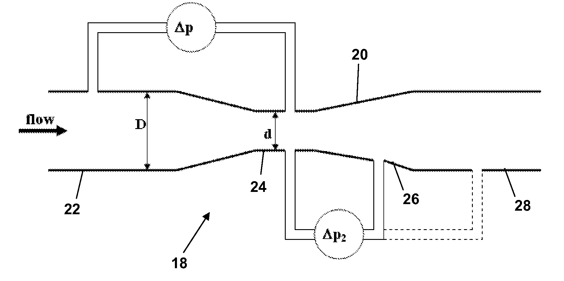
[0040]The present invention provides an apparatus and method for measuring the mass flow rate (qm) of a multi-phase fluid flow. The apparatus and the method are particularly useful for high viscosity multi-phase fluids.

[0041]The apparatus according to the present invention is an in-line apparatus and it is used to determine the Reynolds number, Re, and the discharge coefficient, Cd, of a venturi applied to multi-phase fluid flow, and based on using multiple pressure differentials. Preferably, a single venturi tube and at least two pressure differential measurements are used to determine the Reynolds number and discharge coefficient, and from those variables the mass flow rate, qm, of the multi-phase fluid flow may be determined.

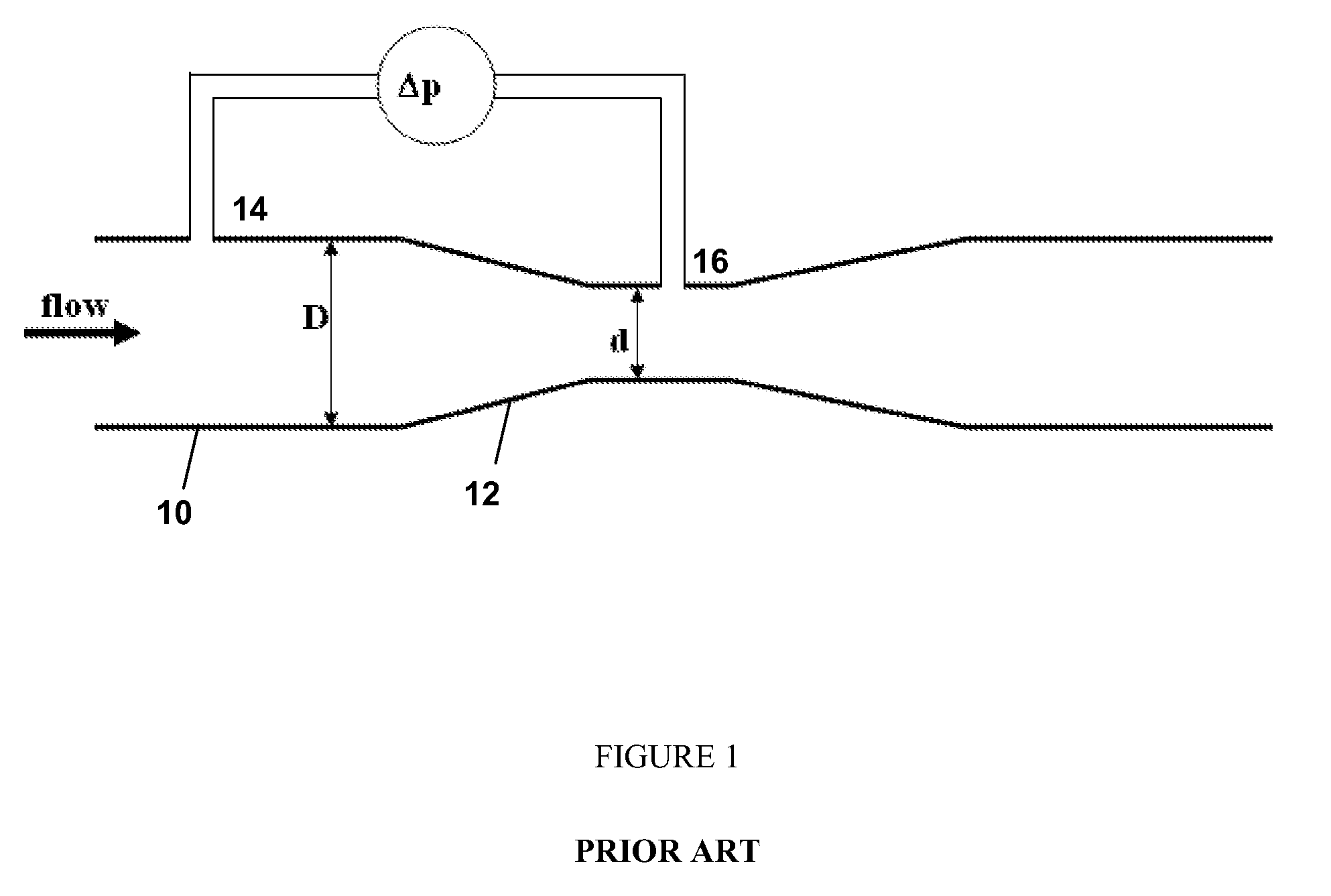
[0042]A schematic side view of a prior art example of a conduit 10 having a venturi 12 and the associated differential pressure measurement, Δp, is shown in FIG. 1. The differential pressure is measured by a pressure sensor 14 near the conduit taking a pressu...


PUM


Abstract

An apparatus and method for measuring a mass flow rate of a multi-phase fluid flowing through a conduit. The apparatus includes a differential pressure element located in the conduit, wherein a first differential pressure measurement device is in communication with the multi-phase fluid between a first and second position across the differential pressure element and is able to measure a first fluid differential pressure. A second differential pressure measurement device is in communication with the multi-phase fluid between a third and fourth position across the differential pressure element and is able to measure a second fluid differential pressure. A processor is in communication with the first and second differential pressure measurement devices, and is able to calculate the Reynolds number and discharge coefficient using the first and second fluid differential pressures. The processor is also capable of calculating the mass flow rate by using the Reynolds number and discharge coefficient.

Description

CROSS-REFERENCE TO RELATED APPLICATION[0001]The present application is based on and claims priority to European Patent Application No. EP08170400, filed Dec. 1, 2008.TECHNICAL FIELD[0002]This invention relates to an apparatus and a method of measuring the mass flow rate of a fluid. In particular, the present invention relates to a flow meter apparatus and a method of measuring the mass flow rate of a fluid particularly for use in measuring the mass flow rate of a multi-phase fluid flow.BACKGROUND ART[0003]The present invention generally relates to flow rate measurements using differential pressure based flow meters with applications in the oil and gas, as well as food industries, but with particular application to multi-phase fluid flow and heavy oil fluid flow.[0004]The standard ISO 5167 describes the manufacture, application and installation requirements of differential pressure based flow measurement devices. Typically different types of measurement devices include an orifice pla...

Claims


Application Information

Patent Timeline
IPC IPC(8): G01F1/44
CPCG01F1/44G01F1/88G01F1/74
Inventor PINGUET, BRUNOTHERON, BERNARDPARRY, ANDREW
Owner SCHLUMBERGER TECH CORP
Why Eureka
Try Eureka