

Switch grass fuel objects with high heat output and reduced air emissions designed for large-scale power generation
a technology of high heat output and power generation, applied in the direction of biofuels, fuels, waste based fuels, etc., can solve the problems of increasing cost, cumulative environmental impact, and decreasing supply, and achieve the effect of reducing air emissions and heating heat valu
Inactive Publication Date: 2010-06-10
RENEWAFUEL
View PDF47 Cites 19 Cited by
- Summary
- Abstract
- Description
- Claims
- Application Information
AI Technical Summary
Benefits of technology
The patent describes finding out that this new type of fuel can be used right away in current solid fuel energy facilities without causing any problems. It also burns very well and produces less harmful pollutants than traditional fossil fuels.
Problems solved by technology
The patent text discusses the need for a new type of fuel that is derived from natural sources and does not contain any conventional fossil fuels. This new fuel has a high heating value, is consistent in nature, low in moisture, can be made at low cost, can be transported and handled at low cost, can be used in existing solid fuel systems with little or no modifications, has lower emissions than fossil fuels, and is specifically adapted for use in modern power plant installations. The technical problem addressed in this patent is the need for a new, cost-effective, and environmentally friendly fuel that can be used in existing solid fuel systems and power plant installations to reduce the environmental impacts associated with traditional fossil fuels.
Method used
View moreImage
Smart ImageViewing Examples

Examples
example
Switch Grass Fuel Object
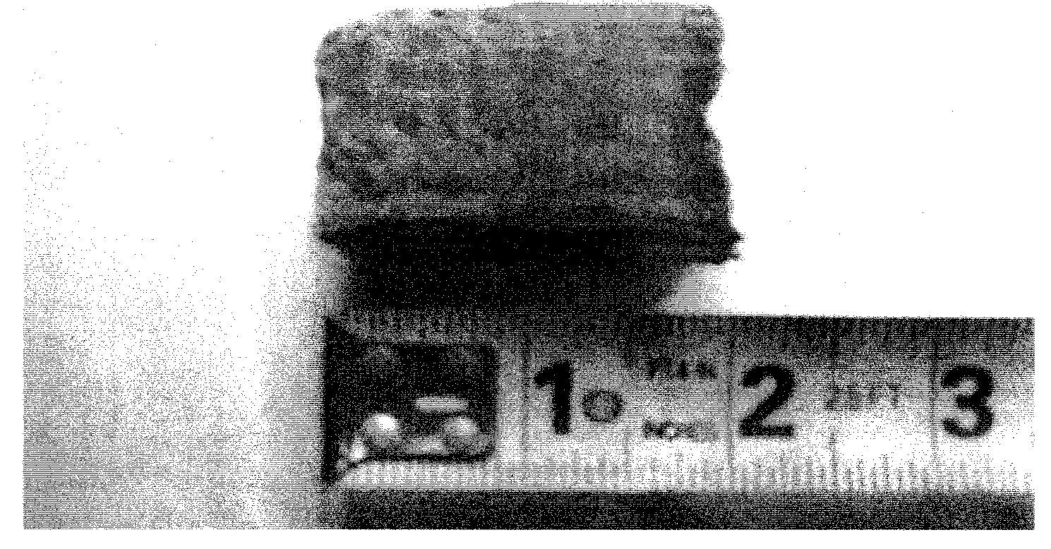
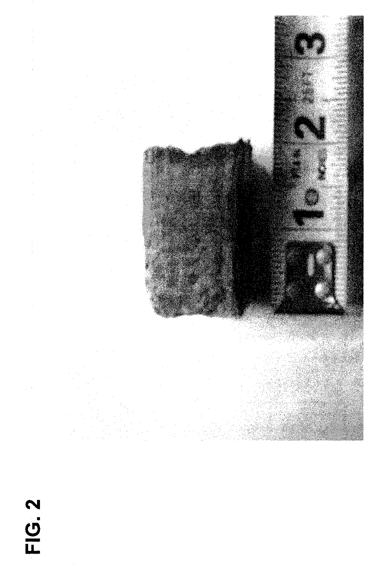
[0042]A fuel object derived from switch grass and wood was produced and was substantially free of coal. The switch grass fuel object was substantially cylindrical in shape with a length of 5.4 cm and a diameter of 2.6 cm.
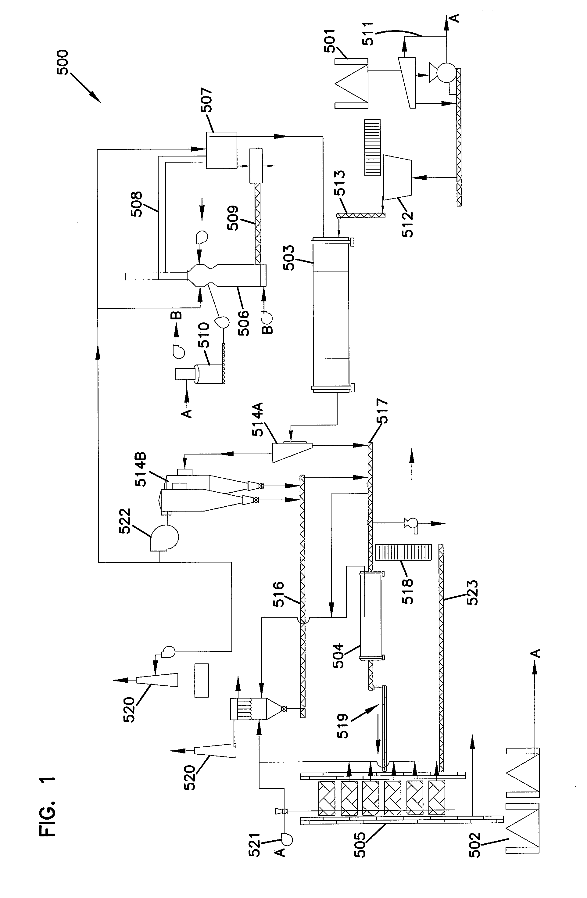
[0043]FIG. 1 shows an embodiment of the invention.
Volume14.04 cm3Moisture content 8.27 wt. %Amount of particulate derived from 63.2 wt. %switch grass-fiber size 80 to 25,000micronsAmount of particulate derived from 34.4 wt. %wood fiber-fiber size 100 to 30,000micronsSodium bicarbonate (inorganic base) 2.4 wt. %
[0044]In testing, this switch grass fuel object provided about 7,386 BTU / pound (lb.).
Login to View More PUM
 Abstract
A Novel fuel object comprised of a proportion of switch grass and a proportion of wood fiber combined with a basically reacting compound. The fuel comprises fiber of the appropriate size and moisture content combined with an inorganic base. An appropriately sized fuel object is readily manufactured, provides high heat output, is consistent in fuel characteristics, and is sized and configured for use in power generation facilities. Based on fiber selection and processing, the fuel object may be used in a variety of current power generation technologies including stoker, fluidized bed, gasifier, cyclonic, direct-fired, and pulverized coal technologies, and results in significant reduction of air emissions (including sulfur dioxide, nitrogen oxides, hydrochloric acid, carbon monoxide, carbon dioxide, and mercury) compared to coal with no loss of boiler or furnace efficiency.
Description
Login to View More Claims
Login to View More Application Information
Patent Timeline
 OwnerRENEWAFUEL