Pneumatic Tire

Inactive Publication Date: 2010-06-10
TOYO TIRE & RUBBER CO LTD
View PDF7 Cites 6 Cited by
  • Summary
  • Abstract
  • Description
  • Claims
  • Application Information

AI Technical Summary

Benefits of technology

[0013]The present invention is made in view of the above circumstances, and an object thereof is to provide a pneumatic tire which can prevent a light from being generated in a side wall portion while suppressing a man hour which is necessary for working a recessed stripe in a mold.
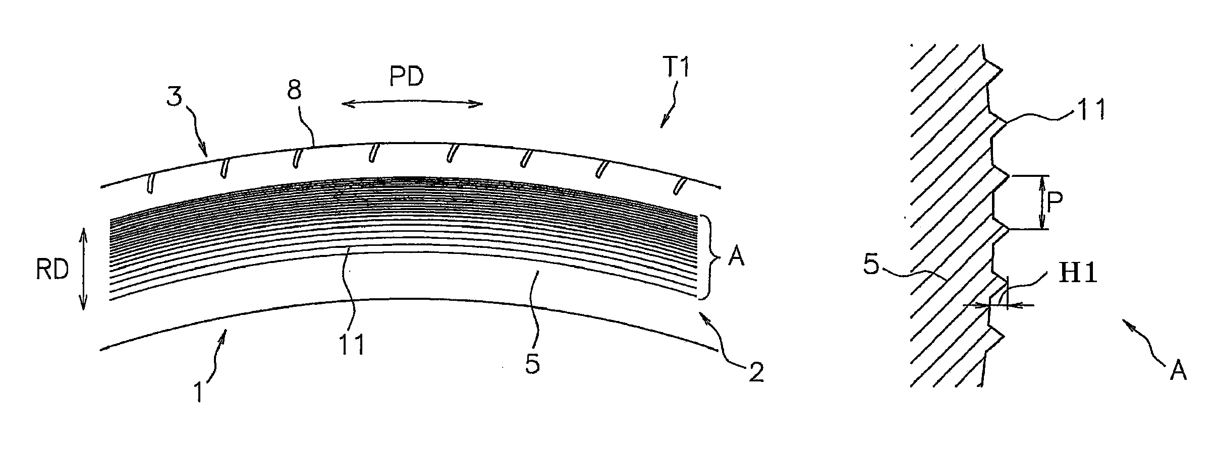
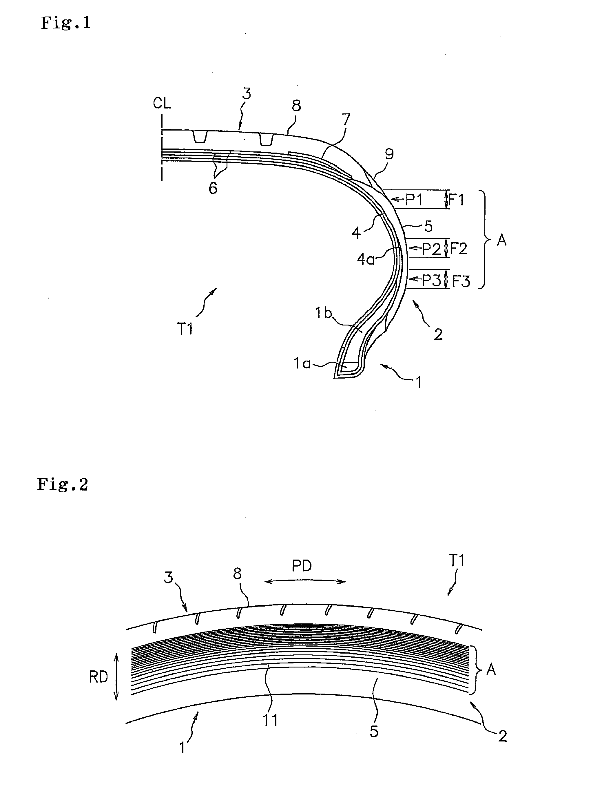
[0015]According to the structure mentioned above, since a concavo-convex region constructed by the projecting line extending in the tire circumferential direction is provided in such a manner as to include the position where the light tends to be generated, the rubber flow of the side rubber is promoted in the tire circumferential direction at a time of the vulcanization molding, and it is possible to suitably suppress the light which tends to be generated along the tire circumferential direction. Further, since an arranged density of the protruding lines becomes larger toward an outer side in a tire diametrical direction, it is possible to obtain an effect of promoting the rubber flow in the tire diametrical direction, and the air is easily let out from the region in which the light tends to be generated. As a result, it is possible to effectively prevent the light from being generated in the side wall portion.
[0016]As mentioned above, it is a fact that the light tends to be generated in the peripheral region of the member end, and the dispersion on the process tends to be generated in the member end. However, in the present invention, since the concavo-convex region having a certain degree of broadness is provided in such a manner as to include the position where the light tends to be generated, it is possible to inhibit the light from being generated without being particularly affected by the dispersion of the member end. Further, in the present invention, since it is possible to reduce the man hour which is necessary for working the recessed stripe in the mold, in comparison with the case of being provided with a lot of protruding lines extending in the tire diametrical direction or the direction which is inclined from the tire diametrical direction, it is possible to reduce the replacing frequency of the tool so as to inhibit the joint line of the projecting lines from appearing, as well as avoiding the sudden rise of the mold working cost.
[0018]According to the structure mentioned above, the same operation and effect as mentioned above can be achieved. That is, the rubber flow of the side rubber is promoted in the tire circumferential direction at a time of the vulcanization molding, and it is possible to suitably suppress the light which tends to be generated along the tire circumferential direction. Further, since a height of the protruding lines becomes larger toward an outer side in a tire diametrical direction, it is possible to obtain an effect of promoting the rubber flow in the tire diametrical direction, and the air is easily let out from the region in which the light tends to be generated. As a result, it is possible to effectively prevent the light from being generated in the side wall portion.
[0019]In the structures mentioned above, it is preferable that the arranged density of the projecting lines gradually becomes larger toward the outer side in the tire diametrical direction. Accordingly, it is possible to arrange the projecting lines in a gradation manner so as to achieve a decorative effect, as well as enhancing the effect of promoting the rubber flow of the side rubber in the tire diametrical direction. Further, in the case that the height of the projecting lines is changed, since it is possible to obtain the effect of promoting the rubber flow in the tire diametrical direction by the change of the arranged density of the projecting lines in addition thereto, it is possible to smoothly let out the air from the region in which the light tends to be generated.

Problems solved by technology

At this time, it is necessary to suitably let out air existing between the outer surface of the side wall portion and the inner peripheral surface of the mold, and if the air is trapped without smoothly letting out the air, a concave scratch called a light is generated due to a fault of a rubber flow, and there is a case that an appearance of the tire is deteriorated.
However, since the vent holes are set in a dotted manner on a circumference of the side wall portion, there is a case that the air fails to escape, and the vent holes cannot securely prevent the light.
Further, since a rubber projection called a spew is formed on the outer surface of the side wall portion, at the position where the vent hole is set, and a trace after cutting the spew remains like a stub, there is a risk that the appearance of the tire is deteriorated if the number of the vent holes is increased blindly.
There can be considered that the vent hole is set aiming at a position of the member end, however, it is a fact that the member end tends to generate a dispersion on a process, and a light countermeasure only by the vent hole is not very effective.
In Japanese Unexamined Patent Publication Nos. 2001-163018, 2004-17829, 11-198614, and 11-291722, there is described a pneumatic tire in which an outer surface of a side wall portion is provided with a lot of projecting lines (ridges) extending to a tire diametrical direction or a direction which is inclined from the tire diametrical direction, however, it is considered that they cannot sufficiently inhibit the light as mentioned above from being generated.
In order to suppress the light in the side wall portion, it is very important to promote the rubber flow of the side rubber at a time of the vulcanization molding so as to make the air easily let out, however, the structure mentioned above cannot particularly promote the rubber flow.
Further, recessed strips corresponding to the projecting lines are provided in the inner peripheral surface of the mold which is pressed against the side wall portion, however, in the tire provided with a lot of protruding lines extending in the tire diametrical direction or the direction which is inclined from the tire diametrical direction, there is a problem that a man hour which is necessary for working the recessed strips is increased, and a mold working cost suddenly rises widely.
Further, a tool tends to wear out in an early stage due to a lot of working amount, and there is a risk that a joint line appears in the projecting line so as to deteriorate the appearance of the tire, if the tool is replaced by a new one in the process of working the recessed stripe.

Method used


Image

  • Pneumatic Tire
  • Pneumatic Tire
  • Pneumatic Tire

Examples


example 1

[0061]As shown in FIG. 7, the outer surface of the side wall portion was provided with the concavo-convex region formed by arranging a lot of projecting lines extending in the tire circumferential direction in parallel in the tire diametrical direction, and the arranged density of the projecting lines became larger toward the outer side in the tire diametrical direction. The concavo-convex region was intermittently provided along the tire circumferential direction, and the opening angle thereof was set within 45°. The size of the concavo-convex region and the height and the cross sectional shape of the projecting line were set to the same as the comparative example 2. The pitch of the projecting lines was set between 0.8 and 1.0 mm in the region F1, between 1.0 and 2.0 mm in the region F2, and between 2.0 and 3.0 mm in the region F3.

example 2

[0062]As shown in FIG. 8, the outer surface of the side wall portion was provided with the concavo-convex region formed by arranging a lot of projecting lines extending in the tire circumferential direction in parallel in the tire diametrical direction, and the arranged density of the projecting lines became larger toward the outer side in the tire diametrical direction. Further, the concavo-convex regions were intermittently provided along the tire circumferential direction, and the opening angle thereof was set so as to exceed 45°. The size of the concavo-convex region and the height, the cross sectional shape and the pitch of the projecting line were set to the same as the example 1.

example 3

[0063]Example 3 was structured in the same manner as the example 1 except the matter that the concavo-convex region is continuously provided annularly along the tire circumferential direction as shown in FIG. 9. Results of the evaluation are shown in Table 1.

TABLE 1Working timeof projectingGenerating condition of lightline (Hr / bothRegion F1Region F2Region F3faces)ComparativeLarge: 4Middle: 2Small: 1 2.0 hoursexample 1ComparativeMiddle: 2Small: 1None28.0 hoursexample 2ComparativeNoneNoneNone76.0 hoursexample 3Example 1Very small: 1NoneNone10.0 hoursExample 2NoneNoneNone12.0 hoursExample 3Small: 2Very small:None15.0 hours1

[0064]As shown by the results of Table 1, in the examples 1 to 3, it is possible to prevent the light from being generated in the side wall portion in comparison with the others. The light in the example 3 is generated in the region between the concavo-convex regions, and the light is not generated in the concavo-convex region. In the comparative example 3, a lot of ...


PUM


Abstract

A pneumatic tire has a pair of bead portions, side wall portions, a tread portion, and a carcass ply rolled up in its end portion so as to pinch a bead filler. An outer surface of the side wall portion is provided with a concavo-convex region formed by arranging a lot of projecting lines extending in a tire circumferential direction in parallel in the tire diametrical direction, and an arranged density of the projecting lines becomes larger toward the outer side in the tire diametrical direction. An outer peripheral end of the concavo-convex region is positioned in the outer side than a position where an interface between a tread rubber and a side rubber is exposed, and an inner peripheral end of the concavo-convex region is positioned in an inner side than a leading end of the bead filler.

Description

BACKGROUND OF THE INVENTION[0001]1. Field of the Invention[0002]The present invention relates to a pneumatic tire in which a lot of projecting lines (ridges) are formed on an outer surface of a side wall portion.[0003]2. Description of the Related Art[0004]In a vulcanization molding of a tire, a pressure and a heat are applied for a fixed time to a green tire in a state in which an outer surface of a side wall portion is pressed against an inner peripheral surface of a mold. At this time, it is necessary to suitably let out air existing between the outer surface of the side wall portion and the inner peripheral surface of the mold, and if the air is trapped without smoothly letting out the air, a concave scratch called a light is generated due to a fault of a rubber flow, and there is a case that an appearance of the tire is deteriorated.[0005]The mold used for the vulcanization molding of the tire is generally provided with a ventilation hole called a vent hole for letting out the ...

Claims


Application Information

Patent Timeline
IPC IPC(8): B60C13/02
CPCY10T152/10819B60C13/02
Inventor TAKAHASHI, TOSHIHIKO
Owner TOYO TIRE & RUBBER CO LTD
Why Eureka
Try Eureka