Separable Ball Valve Apparatus and Ball Valve Assembly

a technology of separable ball valves and valve assemblies, which is applied in the direction of valve housings, valve operating means/releasing devices, transportation and packaging, etc., can solve the problems of affecting the flow of the valve, and requiring a lot of manpower to block the pipe, so as to achieve convenient blocking of the flow path and separating or connecting the pipe

Inactive Publication Date: 2010-06-10
KOREA ATOMIC ENERGY RES INST +1
View PDF6 Cites 37 Cited by
  • Summary
  • Abstract
  • Description
  • Claims
  • Application Information

AI Technical Summary

Benefits of technology

[0009]Accordingly, it is an object of the present invention to provide a separable ball valve apparatus and a separable ball valve assembly that are capable of conveniently blocking a flow path and separating or connecting pipes.
[0010]It is another object of the present invention to provide a separable ball valve apparatus and a separable ball valve assembly that are capable of removing necessity of a separate coupling space for blocking a flow path and attaching or detaching pipes to improve space utilization.
[0011]It is still another object of the present invention to provide a separable ball valve apparatus and a separable ball valve assembly that are capable of preventing exposure of fluid remaining in a pipe after blocking a flow path and separating the pipe, thereby securing safety.

Problems solved by technology

However, it takes much time and manpower to block the pipe, especially, the welding requires very complicate processes.
Here, the pipe removed cannot be reused at different places due to the length or the bent shape thereof, and cannot be easily connected to a new pipe.
While the block member can block the toxic fluids such as radioactive liquids, the toxic fluids may remain on an exposed part of the block member after separation of the pipe to be leaked to the exterior.

Method used


Image

  • Separable Ball Valve Apparatus and Ball Valve Assembly
  • Separable Ball Valve Apparatus and Ball Valve Assembly
  • Separable Ball Valve Apparatus and Ball Valve Assembly

Examples


first embodiment

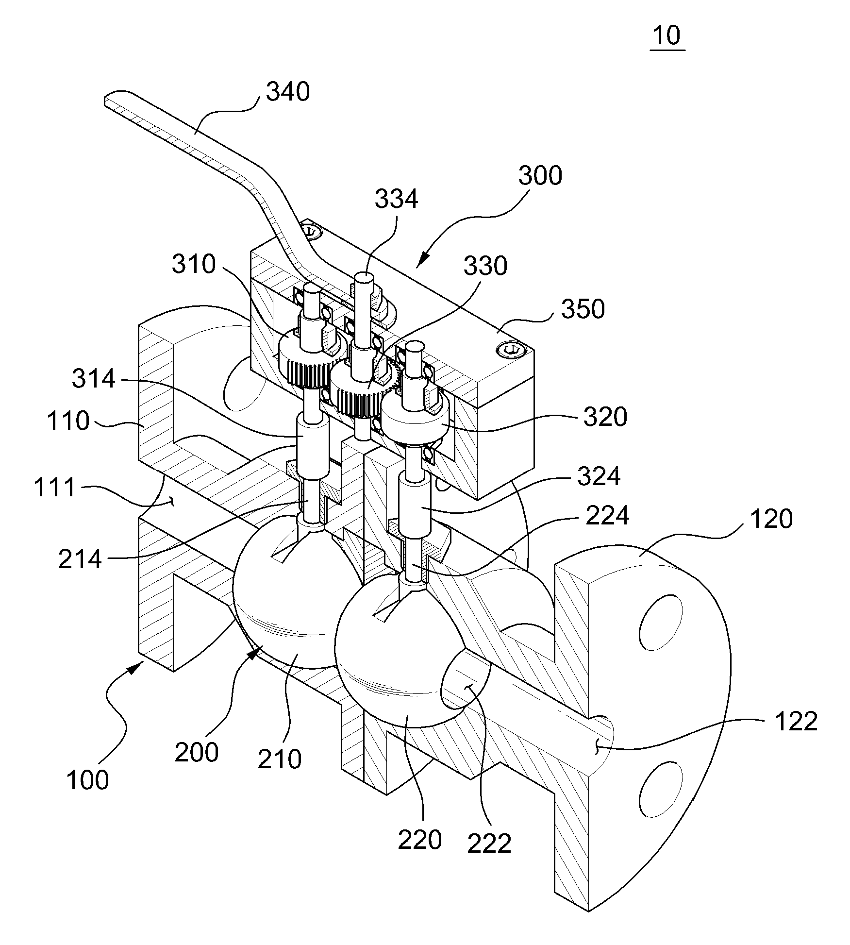
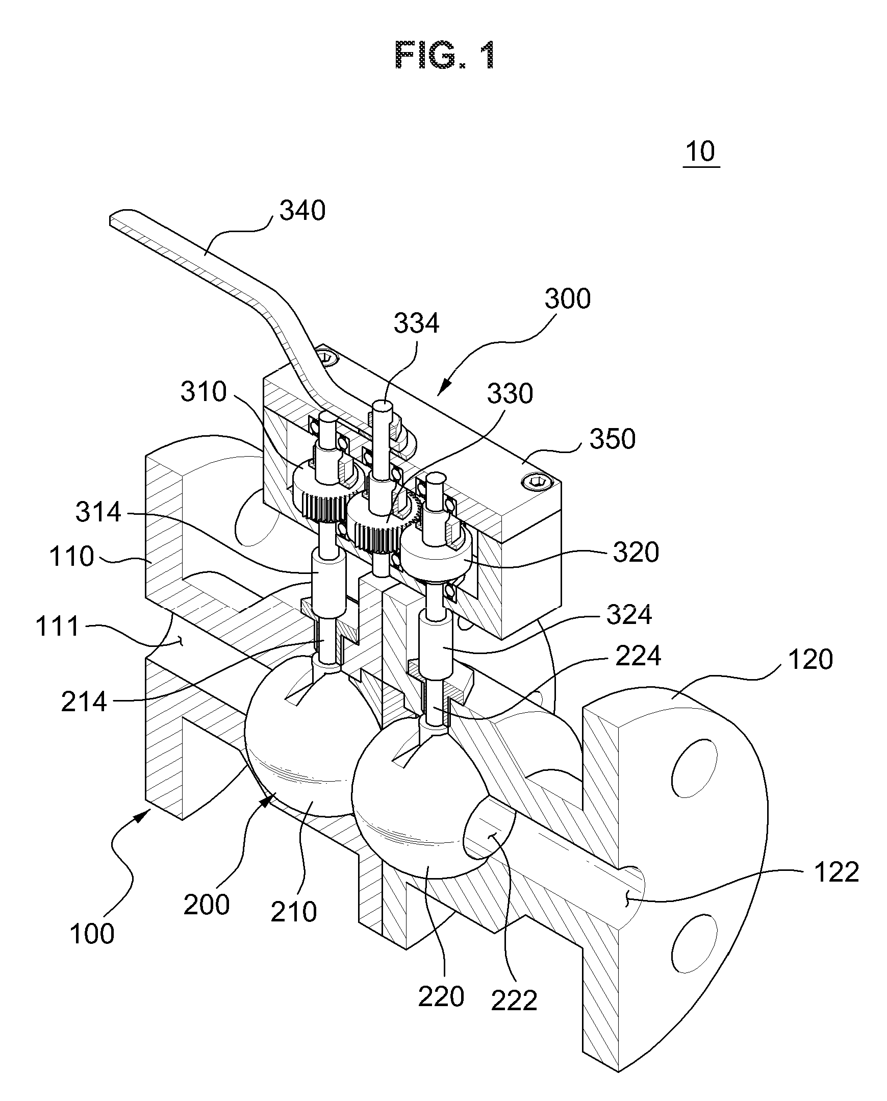
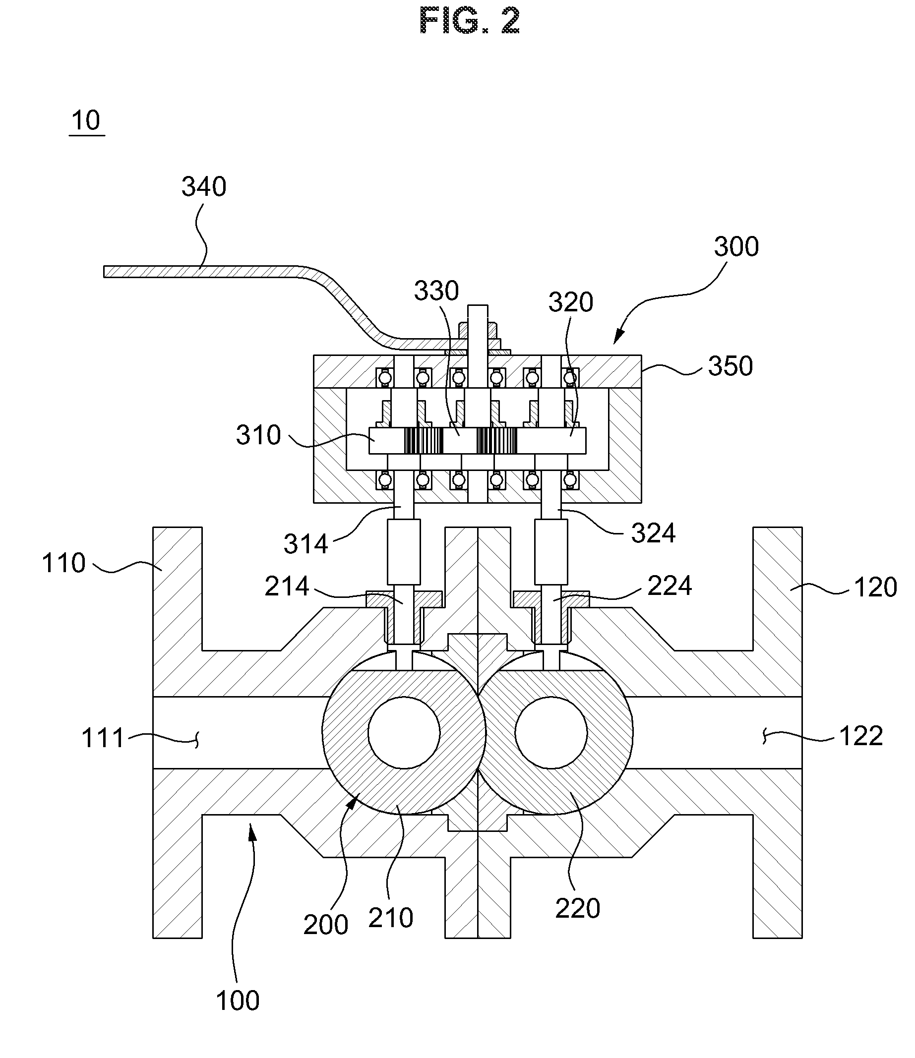
[0052]According to the present invention for the gear train mechanism, the gear train may be constituted by spur gears. Specifically, the gear train includes a first gear 310, a second gear 320, and a central gear 330, which are spur gears.

[0053]The central gear 330 is disposed between the first and second gears 310 and 320, and in contact with the first and second gears 310 and 320. The central gear 330 has a toothed part 332 formed at a portion of a circumference thereof. In this embodiment, the central gear 330, the first gear 310, and the second gear 320 have the same diameter. Accordingly, the toothed part of the central gear 330 is formed at the only half of the circumference of the central gear 330 (e.g. 180° of a central angle). If the first gear 310 and the second gear 320 have the same diameter and the diameter of the central gear is twice longer than the diameter of one of the first and the second gears 310 and 320, the toothed part 332 of the central gear is formed at th...

second embodiment

[0078]FIGS. 5A to 5C are cross sectional plan views showing a process of closing a flow path using a separable ball valve apparatus 10 in accordance with the present invention.

[0079]According to the second embodiment of the present invention for the gear train mechanism, the gear train may be constituted by a rack and pinion gear. That is, the gear train includes first and second gears 1310 and 1320 as pinion gears, and a central gear 1330 as a rack gear.

[0080]Since the rack and pinion gear of the second embodiment is similar to the spur gears of the first embodiment, like reference numerals denote like elements, and description thereof will be omitted for the convenience of description. Hereinafter, different parts from the first embodiment will be described.

[0081]A toothed part 1312 of the first gear 1310 and a toothed part 1322 of the second gear 1320 may be partially or entirely formed along circumferences thereof. A toothed part 1332 of the central gear 1330 adjacent to the fir...

third embodiment

[0084]FIG. 6 is a schematic view showing a block unit of a separable ball valve apparatus 10 in accordance with a gear train of the present invention.

[0085]According to the third embodiment of the present invention for the gear train mechanism, the gear train may be constituted by a bevel gear. That is, the gear train includes a first gear 2310, a central gear 2330, and a second gear 2320, which are bevel gears.

[0086]FIG. 7 is a vertical sectional view of a closed state of a separable ball valve apparatus in accordance with a variant embodiment of a pipe member.

[0087]Since the separable ball valve apparatus in accordance with a variant embodiment of the pipe member is similar to the separable ball valve apparatus 10, like reference numerals denote like elements, and description thereof will be omitted for the convenience of description. Hereinafter, difference between the variant embodiment and the above embodiments will be described.

[0088]In the variant embodiment, third and fourth...


PUM


Abstract

A separable ball valve apparatus and ball valve assembly capable of selectively opening / closing a separable flow path are provided. The separable ball valve apparatus comprises a separable pipe member having a flow path through which fluid flows, a ball member having at least two balls disposed in the pipe member, opening and closing the flow path, and adjacent to each other, and an opening / closing member configured to control the ball member to open / close the flow path, wherein the balls have through-holes, respectively, and the opening / closing member includes a gear train configured to control the opening / closing of the at least two balls. Therefore, it is possible to simply open / close pipes having the flow path and detachably attach the pipes, increase space utilization due to removal of a separate coupling space for attachment / detachment of the pipes, and simultaneously open / close the two pipes, which are separated from each other through one operation.

Description

CROSS-REFERENCE TO RELATED APPLICATIONS[0001]This application claims priority to foreign Patent Application KR 10-2008-0125266, filed on Dec. 10, 2008, the disclosure of which is incorporated herein by reference in its entirety.FIELD OF THE INVENTION[0002]The present invention relates to a separable ball valve apparatus and a separable ball valve assembly, and more particularly, to a separable ball valve apparatus and a separable ball valve assembly that can be disposed in a pipe constituted by two detachable parts to simply open and close a flow path.BACKGROUND OF THE INVENTION[0003]In general, fluids are transported through flow paths formed by tubes or pipes. In daily life, tubes and pipes are widely used to transport fluid through in various fields such as water supply and drainage pipes, gas pipes, air conditioner coolant circulation pipes, waste conveyance pipes. In addition, such tubes or pipes are used to transport radioactive liquids from a storage tank to a reservoir for t...

Claims


Application Information

Patent Timeline
Patent Type & Authority Applications(United States)
IPC IPC(8): F16K5/06
CPCF16K5/0647F16K31/535F16K27/067F16K35/14Y10T137/87933F16K31/60
Inventor CHANG, SEOK-KYUSONG, CHUL-HWA
Owner KOREA ATOMIC ENERGY RES INST
Why Eureka
Try Eureka