Valve construction

Inactive Publication Date: 2010-06-10
MCLENNAN WILLIAM ROSS
View PDF11 Cites 16 Cited by
  • Summary
  • Abstract
  • Description
  • Claims
  • Application Information

AI Technical Summary

Benefits of technology

[0013]The present invention relates to an improved valve seal for use with fluid and gas piping and containers. The object of this invention is to provide an

Problems solved by technology

This is very important in, for example, the pharmaceutical industry where dea

Method used


Image

  • Valve construction
  • Valve construction
  • Valve construction

Examples


Embodiment Construction

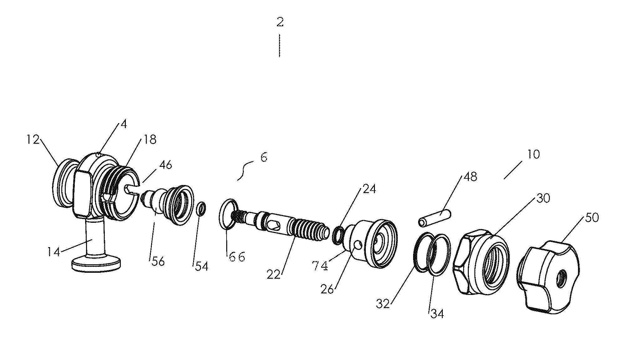
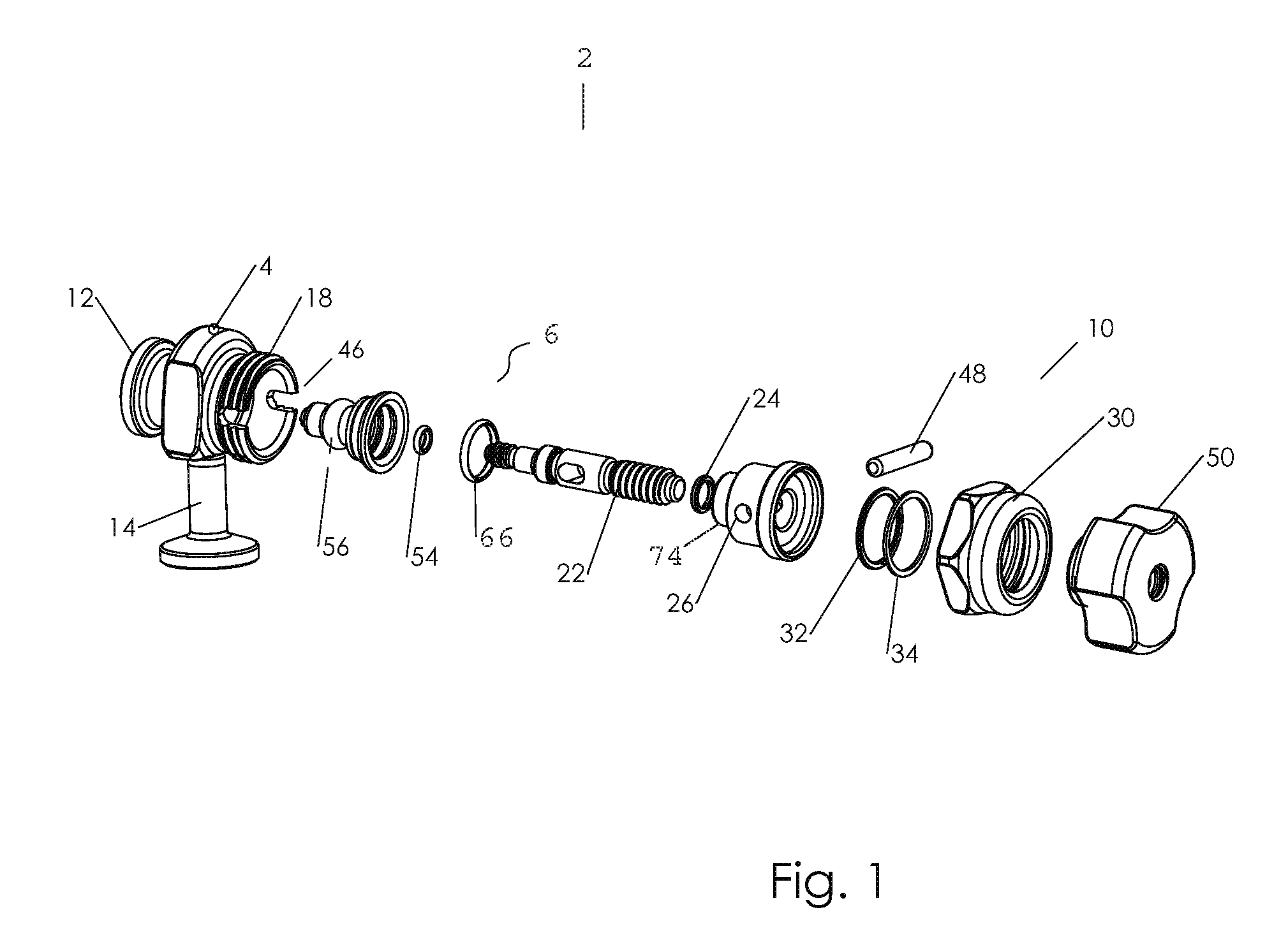
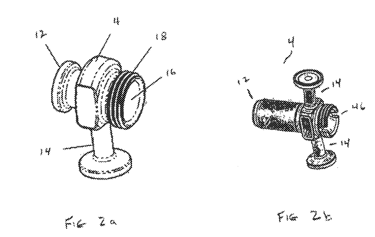
[0027]As required, detailed embodiments of the present invention are disclosed; however, it is to be understood that the disclosed embodiments are merely exemplary of the invention that may be embodied in various forms. The figures are not necessary to scale, and some features may be exaggerated to show details of particular components. Therefore, specific structural and functional details disclosed are not to be interpreted as limiting, but merely as a basis for the claims and as a representative basis for teaching one skilled in the art to variously employ the present invention. Where possible, like reference numerals have been used to refer to like parts in the several alternative embodiments of the present invention described herein.

[0028]The present invention describes a valve assembly utilizing a novel valve seal. Not depicted in the drawings are mechanisms used to operate the valve shaft movement such as an air cylinder or a fast acting cam handle. Multiple valve configuratio...


PUM


Abstract

A valve assembly for sealing and control of a fluid, gas or dry material. The valve assembly includes a seal assembly having a hollow seal, a related valve body, and an actuator assembly. The valve body has a generally circular internal cavity with the seal assembly having a generally tubular solid wall defined tip having a flexible wall portion containing a seal element used to seal against both static and dynamic forces. An actuator assembly actuates the seal assembly. The seal assembly is situated coaxially within the valve internal cavity and thereby defines an internal fluid passageway within the valve body.

Description

CROSS REFERENCE TO RELATED APPLICATIONS[0001]This application claims benefit of U.S. Provisional Application No. 61 / 151,766 filed Feb. 11, 2009 and is a continuation in part of U.S. application Ser. No. 11 / 825,522 filed Jul. 5, 2007 which claims the benefit of U.S. Provisional Application No. 60 / 818,384 filed Jul. 5, 2006, of all which are incorporated by reference in their entirety.FIELD OF THE INVENTION[0002]The present invention relates to fluid and gas piping and containers and more particularly to an improved valve construction for use therewith.BACKGROUND OF THE INVENTION[0003]Manufacturing processes such as those used in the biotech, pharmaceutical and semiconductor industries require a demanding valve which provides for secure closure and also for clean-in-place and steam sterilization. The simple closures currently in use or already known have proven unsatisfactory for these uses.[0004]Common non-pinching valve designs used in these industries are generally based upon the S...

Claims


Application Information

Patent Timeline
IPC IPC(8): F16K51/00F16J15/32
CPCF16K7/16F16K41/103F16K11/04
Inventor MCLENNAN, WILLIAM ROSS
Owner MCLENNAN WILLIAM ROSS
Why Eureka
Try Eureka