Capacitor motor and process for producing the same

a technology of capacitor motor and capacitor, which is applied in the direction of dynamo-electric machines, magnetic circuits characterised by magnetic materials, supports/enclosements/casings, etc., can solve the problems of motor efficiency reduction and greater loss consumed on the windings, and achieve the effect of increasing motor efficiency, reducing magnetic flux density, and increasing efficiency

Inactive Publication Date: 2010-06-10
PANASONIC CORP
View PDF10 Cites 36 Cited by
  • Summary
  • Abstract
  • Description
  • Claims
  • Application Information

AI Technical Summary

Benefits of technology

[0024]The structure and the method discussed above allow the capacitor motor of the present invention to prevent cross sectional areas of the tooth sections and lengths of the windings from increasing, so that the motor can increase its efficiency. The structure and the method also allow enlarging a cross sectional area of the magnetic path of the yoke section without increasing an outer diameter of the stator iron core, so that the magnetic flux density can be lowered and the motor efficiency thus can be increased.

Problems solved by technology

As a result, the length of the windings wound on the tooth sections is obliged to be longer, which invites greater loss consumed on the windings, so that the motor lowers its efficiency.

Method used


Image

  • Capacitor motor and process for producing the same
  • Capacitor motor and process for producing the same
  • Capacitor motor and process for producing the same

Examples


embodiment 1

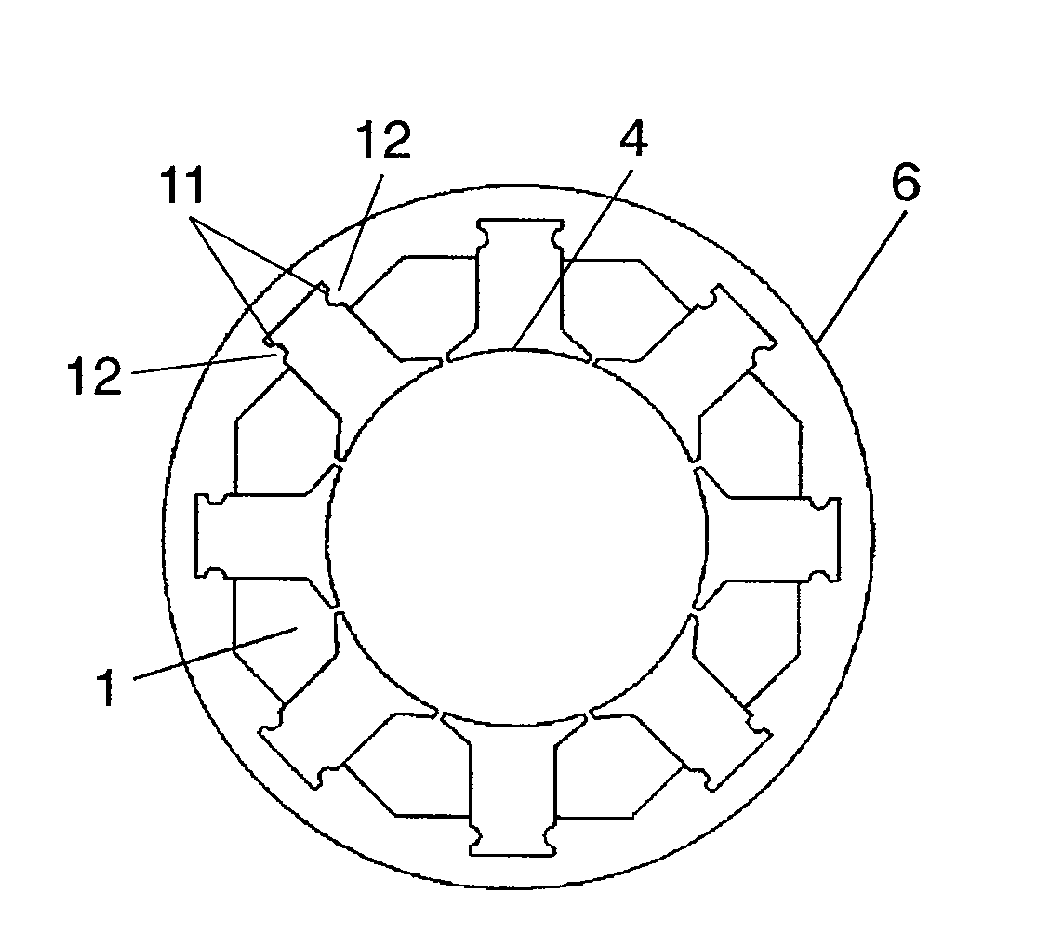
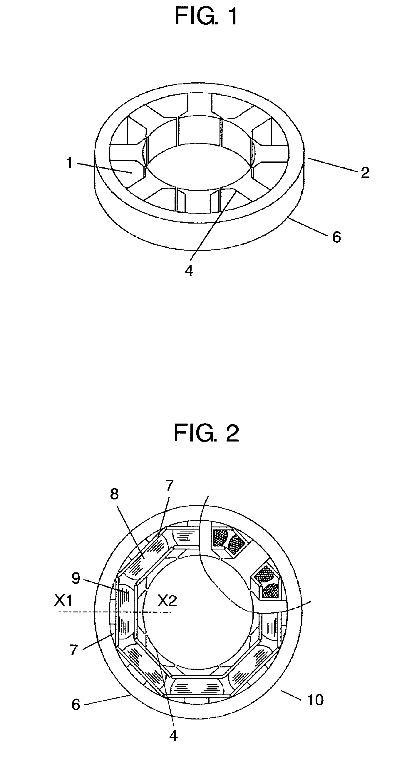
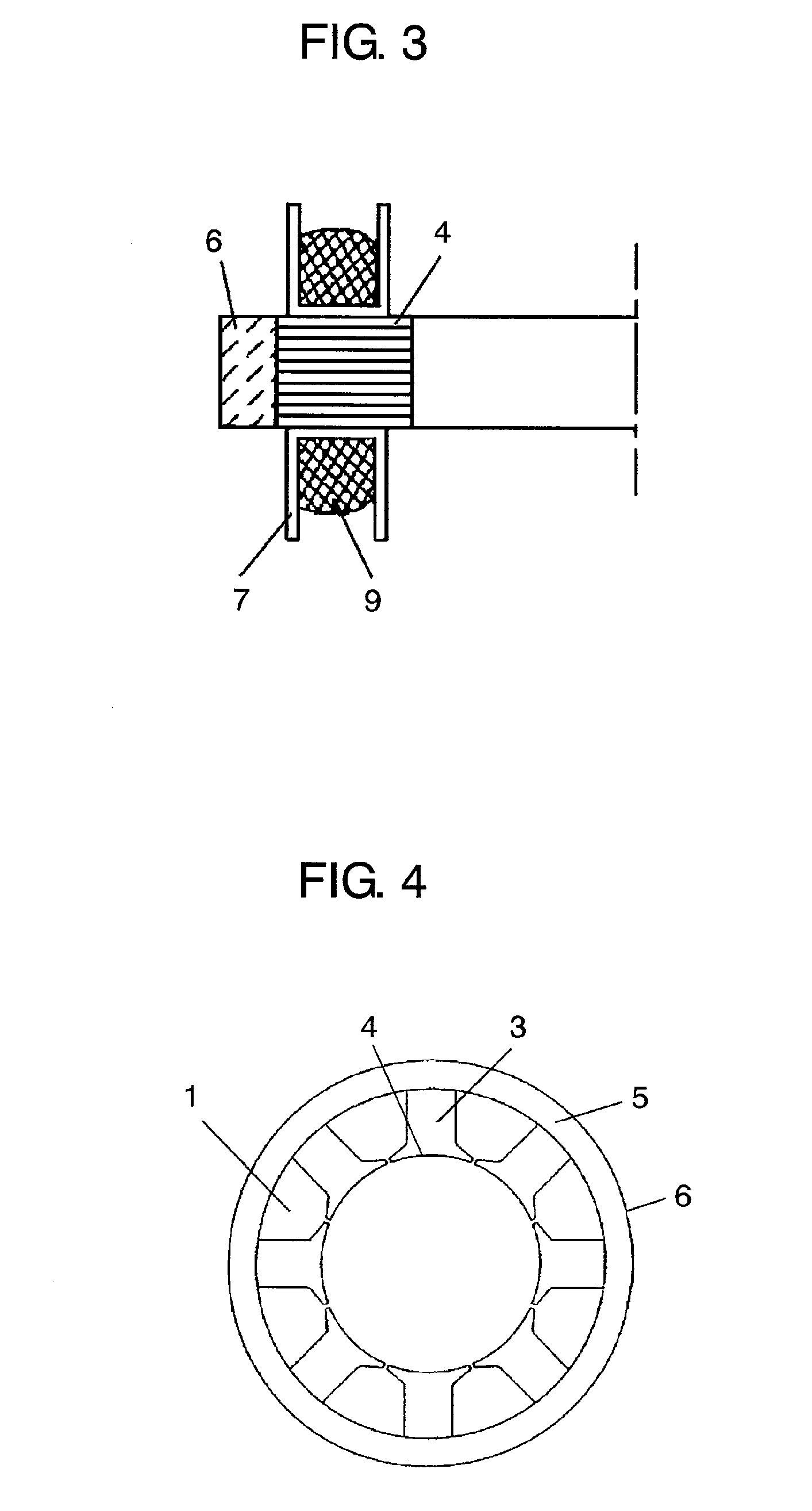
[0089]FIG. 1-FIG. 10 show stators of a capacitor motor in accordance with the first embodiment of the present invention. As these drawings show, the capacitor motor of the present invention includes stator iron core 2 having eight pieces of slots 1. Stator iron core 2 having eight slots 1 is divided into the following two iron-core units, namely, first divided iron-core unit 4 and second divided iron-core unit 6:[0090]eight pieces of first divided iron-core unit 4 each of which mainly forms tooth section 3; and[0091]second divided iron-core unit 6 which forms a magnetic path as yoke section 5 on the outer walls of slots 1 and first divided iron-core units 4. Each one of first divided iron-core units 4 is formed by punching electromagnetic steel plates and layering the steel plates punched out, and each one of tooth sections 3 is mounted with phase-A winding 8 or phase-B winding 9, both of windings 8 and 9 being wound on insulating bobbins 7. Iron-core units 4 mounted with phase-A wi...

embodiment 2

[0097]The second embodiment is demonstrated with reference to FIG. 11-FIG. 13. Similar elements to those in the first embodiment have the same reference marks, and the descriptions thereof are omitted here.

[0098]What are shown in FIGS. 11 and 12 differ from the first embodiment in the following points: Second divided iron-core unit 6A has thickness N along the axial direction, and tooth section 3 of first divided iron-core unit 4 has thickness L along the axial direction. Thickness N is set longer than thickness L. Another point is this: Rotor 14 is provided inside of stator iron core 2, and rotor 14 holds rotor iron core 13 coaxially and rotatably, and rotor iron core 13 has axial thickness M equal to axial thickness L of first divided iron-core unit 6A. Other structures remain unchanged from those of the first embodiment, for instance, second divided iron-core unit 6A is formed of dust core which is made by molding magnetic powder into the given shape, and first divided iron-core ...

embodiment 3

[0102]The third embodiment is demonstrated with reference to FIG. 14-FIG. 15. Similar elements to those in the first and the second embodiments have the same reference marks, and the descriptions thereof are omitted here.

[0103]What are shown in FIGS. 14 and 15 differ from the first and the second embodiments in the following points: Second divided iron-core unit 6A has an axial thickness set longer than that of tooth section 3 of first divided iron-core unit 4. Another point is this: third divided iron-core unit 15 is additionally provided to each one of first divided iron-core units 4 at their front and rear faces along their outer walls as well as at the tips of front and rear faces along their inner walls, both of the front and rear faces being axially disposed and no windings being mounted or wounded thereon. Third divided iron-core unit 15 is formed of dust core which is made by molding magnetic powder into a given shape, so that iron-core unit 15 can be formed into any shape w...


PUM

PropertyMeasurementUnit
magneticaaaaaaaaaa
shapeaaaaaaaaaa
circumferenceaaaaaaaaaa

Abstract

A capacitor motor is formed of a stator including a stator iron core and windings, and a rotor including a rotor iron core. The stator iron core is divided into a plurality of first divided iron-core units having tooth sections and a second divided iron-core unit forming a magnetic path of the first divided iron-core units. The windings are mounted to the tooth sections and accommodated in a plurality of slots formed by the first iron-core units and the second one. The first divided iron-core units are formed by punching electromagnetic steel plates and layering the plates punched out. The second divided iron-core unit is formed by molding magnetic powder into a given shape. The first divided iron-core units and the second one are jointed together by a given means such that the tooth sections can be arranged radially on outer wall of the rotor iron core.

Description

TECHNICAL FIELD[0001]The present invention relates to a capacitor motor including a stator iron core and a stator. The stator iron core is separated into pieces, of which quantity is equal to or more than the number of slots, and formed by combining a layered iron-core unit made by punching electromagnetic steel plates and layering the steel plates punched out with a dust core made by forming magnetic powder into a given shape. The present invention also relates to a method of manufacturing the forgoing capacitor motor.BACKGROUND ART[0002]A conventional capacitor motor has been formed in the following manner: an armature core (hereinafter referred to as a stator iron core) is divided into plural pieces, and the respective pieces are formed of magnetic powder. Stator teeth (hereinafter referred to as tooth sections) are wound by coils (windings), then the tooth sections are integrated into the armature yokes (yoke sections) arranged in an annular shape. This structure is widely known...

Claims


Application Information

Patent Timeline
Patent Type & Authority Applications(United States)
IPC IPC(8): H02K1/02H02K15/12
CPCH02K1/02H02K1/148Y10T29/49009H02K5/02H02K1/185
Inventor NISHIMURA, SHIGEKI
Owner PANASONIC CORP
Why Eureka
Try Eureka