

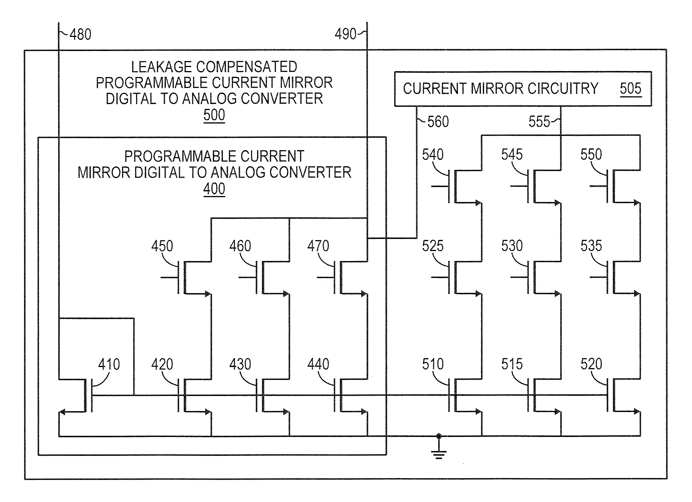
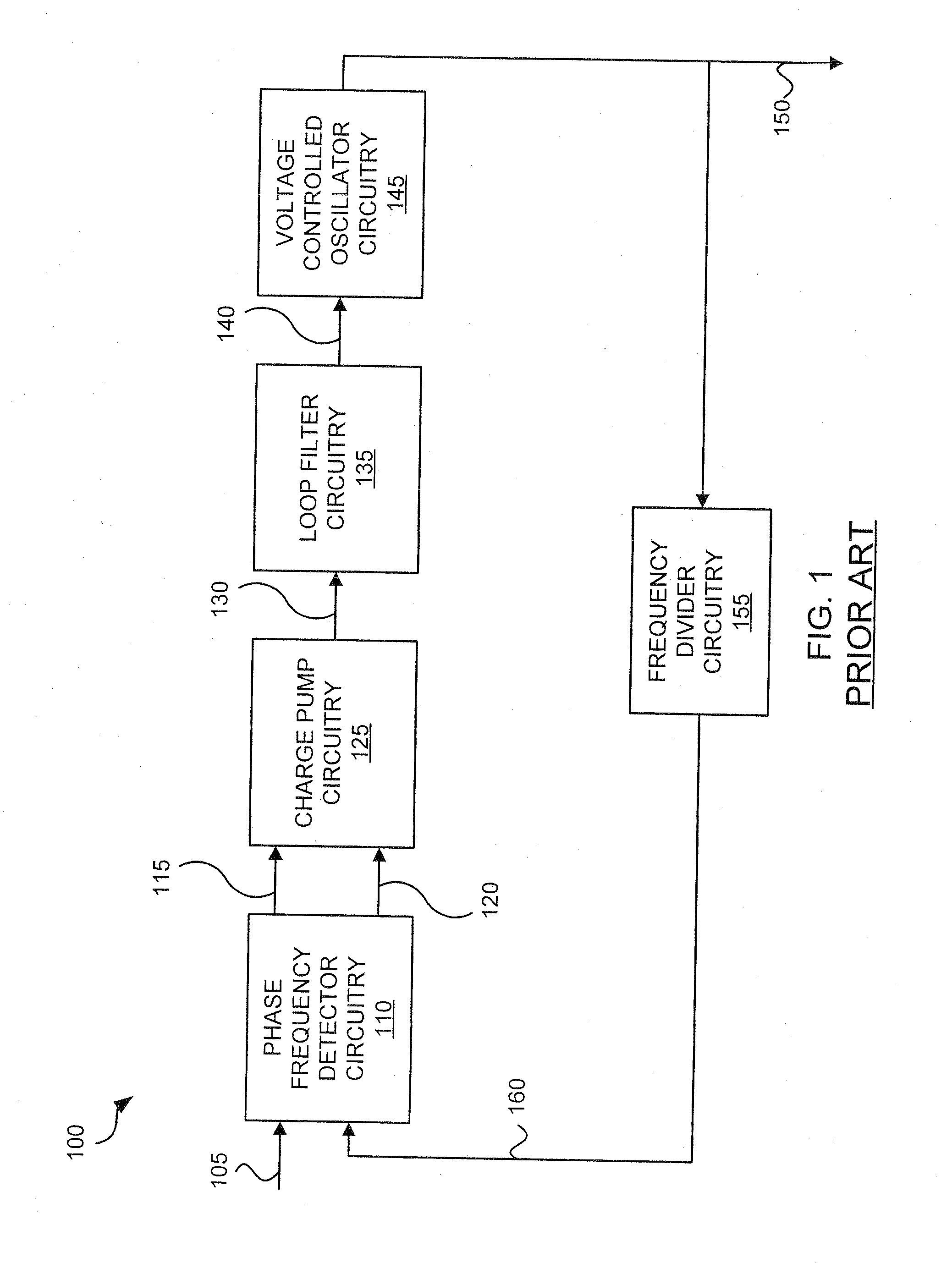
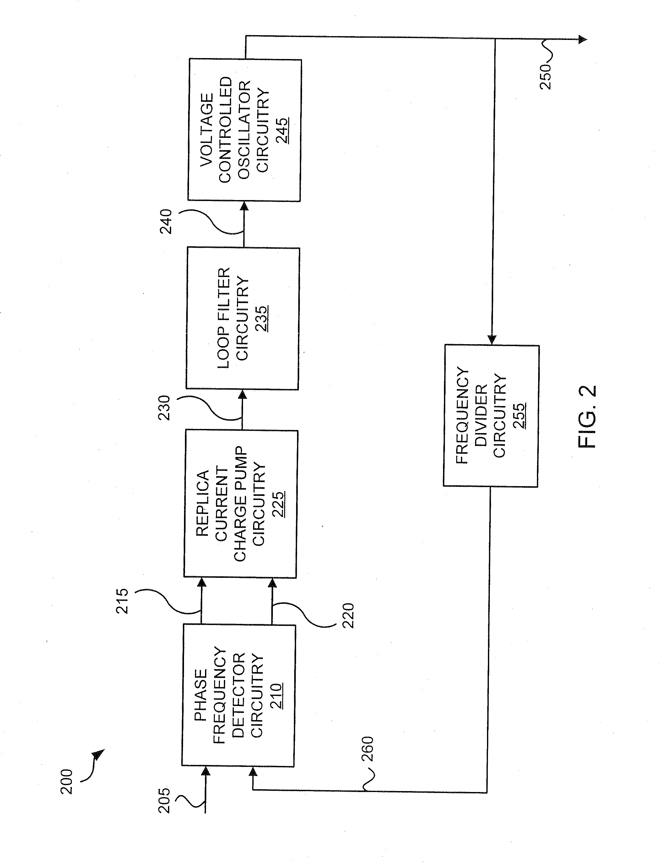
Phase-locked loop circuitry using charge pumps with current mirror circuitry
a current mirror and phase-locked loop technology, applied in the direction of digital-analog converters, automatic control, instruments, etc., can solve the problem that the magnitude of device leakage in deep submicron technologies is often significantly larger than the actual signal being generated, and achieve good resolution, reduce static phase offset, and reduce the effect of static phase offs
- Summary
- Abstract
- Description
- Claims
- Application Information
AI Technical Summary
Benefits of technology
Problems solved by technology
Method used
Image

Examples
Embodiment Construction
[0027]The embodiments discussed herein are illustrative of one example of the present invention. As these embodiments of the present invention are described with reference to illustrations, various modifications or adaptations of the methods and / or specific structures described may become apparent to those skilled in the art. All such modifications, adaptations, or variations that rely upon the teachings of the present invention, and through which these teachings have advanced the art, are considered to be within the scope of the present invention. Hence, these descriptions and drawings should not be considered in a limiting sense, as it is understood that the present invention is in no way limited to only the embodiments illustrated.
[0028]A circuit implementation of the principles disclosed may be implemented using PMOS transistors alone, NMOS transistors alone, parallel combinations of PMOS and NMOS transistors, or other types of transistors. In some embodiments, the parallel comb...
PUM
 Abstract
Description
Claims
Application Information