
Pointing device, data processing device, and data processing system

a data processing system and pointing device technology, applied in the direction of electric digital data processing, instruments, computing, etc., can solve the problems of reducing the reliability of the menu selection system, affecting the selection process, so as to achieve high reliability and reliably prevent unintended selection

Active Publication Date: 2010-06-10
SEIKO EPSON CORP
View PDF3 Cites 17 Cited by
  • Summary
  • Abstract
  • Description
  • Claims
  • Application Information

AI Technical Summary

Benefits of technology

[0009]Consequently, when the cursor position is offset from the desired position when the operation of the operation switch is actually detected, the wrong selection option (wrong menu) is selected by the misplaced cursor. In this type of situation, the pointing device becomes less convenient, and the reliability of the menu selection system is also reduced.
[0029]According to at least one aspect of the present invention, a highly reliable data processing system (e.g., including a three-dimensional input device (pointing device) and a data processing device), for example, can be provided that is capable of reliably preventing unintended selection due to shaking of the pointing device, through the use of an easily implemented method that does not bring increased hardware cost.

Problems solved by technology

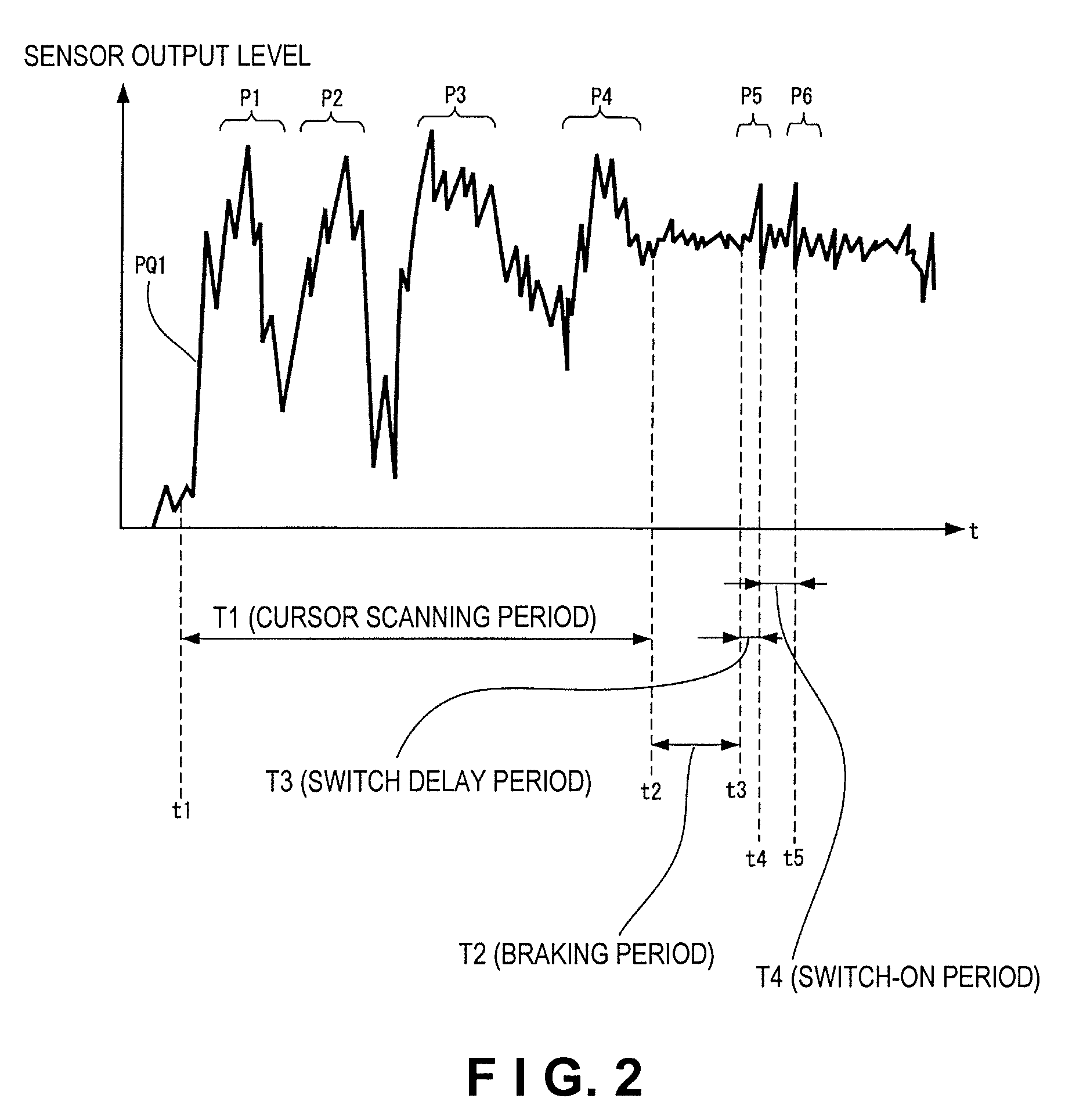
There is generally somewhat of a time delay between the start of operation of the operation switch and the time that operation is actually detected.
In this type of situation, the pointing device becomes less convenient, and the reliability of the menu selection system is also reduced.
Examples of possible measures for addressing this problem include giving each selection option of the menu screen page a large area, employing a switch that requires minimal operating force, and specifically designing the arrangement of the operation button or the like or the function of the operation button or the like, but these measures have limited effectiveness and cannot be considered adequate from the perspective of reliably preventing wrong selection.
Unintended selection of a menu or the like is caused by the cursor position being shifted by shaking of the pointing device that accompanies operation of the operation switch during the delay period from the start of operation of the operation switch to the time that the operation is actually detected.

Method used


Image

  • Pointing device, data processing device, and data processing system
  • Pointing device, data processing device, and data processing system
  • Pointing device, data processing device, and data processing system

Examples


first embodiment

[0040]In the present embodiment, when an operation switch changes from the “off” state to the “on” state, an event to be executed (execution event) is generated based on cursor position information of a time that is a predetermined time prior to the turn-on detection time of the operation switch.

Example of Configuration and Operation of Menu Selection System

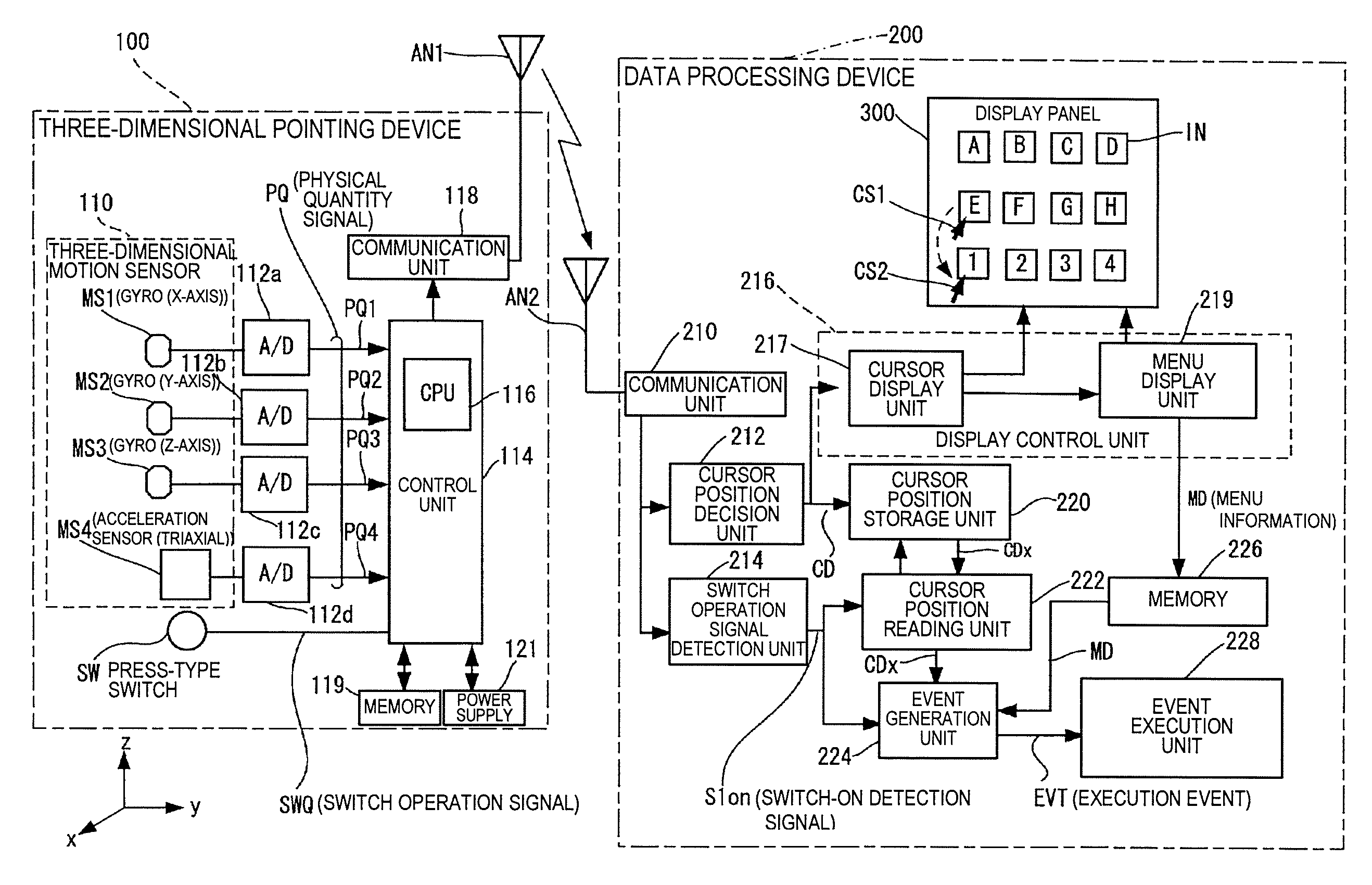
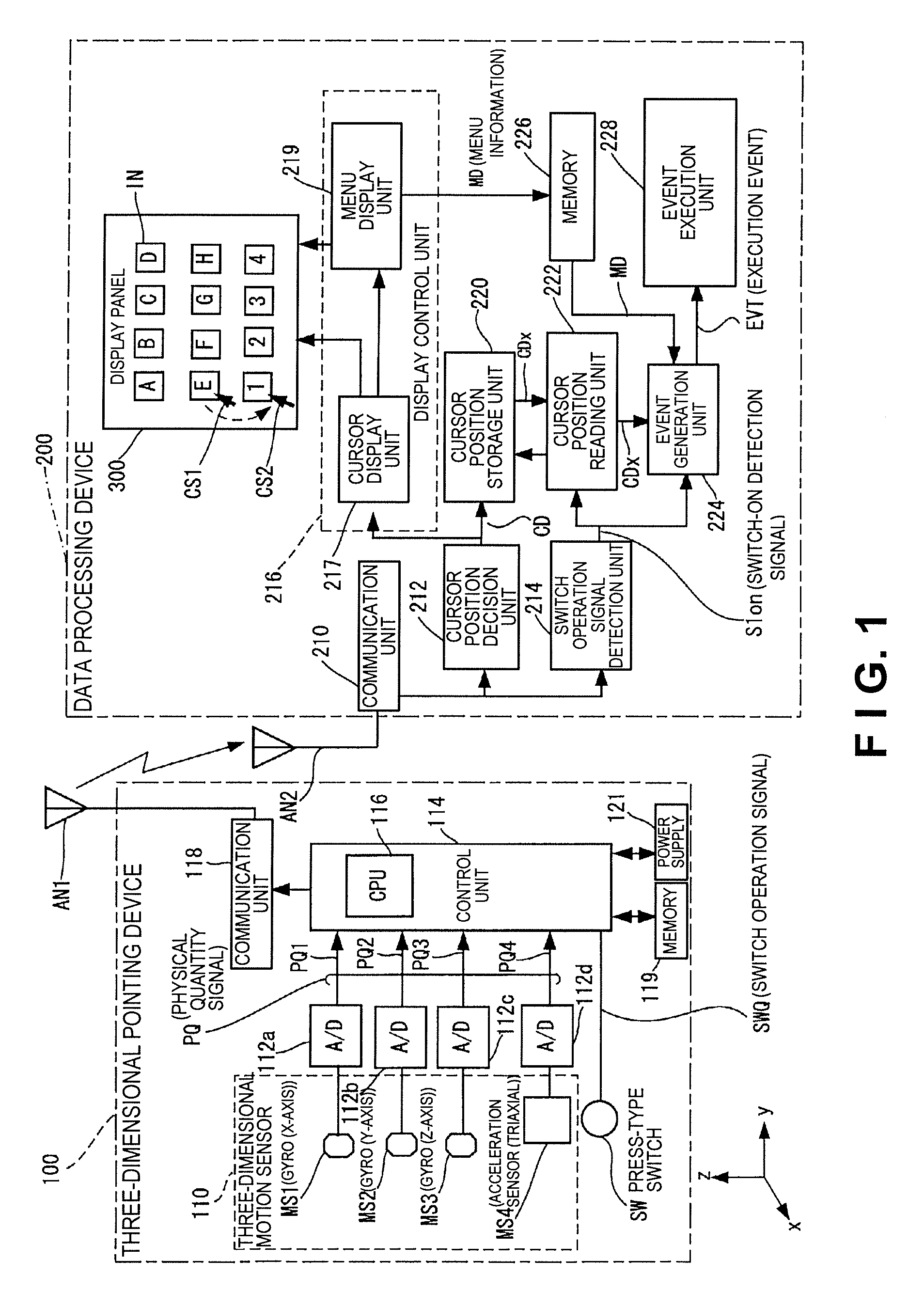
[0041]FIG. 1 is a view showing an example of the configuration of a data processing system (in this instance, a menu selection system). The menu selection system shown in FIG. 1 includes a three-dimensional pointing device 100 and a data processing device 200. The three-dimensional pointing device is an input device having a function for generating a physical quantity signal in response to movement in space (e.g., at least one of orientation, rotation, and translation), and is a three-dimensional mouse, for example. The term “pointing device” refers to an input device in a computer system or the like, and is interpreted in the br...

operation example

[0073]FIGS. 3A and 3B are views showing an example of the specific operation for event generation in the data processing device shown in FIG. 1. As shown in FIG. 3A, Event 1, Event 2, and Event 3 are coordinated on a 1:1 basis with selection options (A, E, 1) displayed on the display panel 300. For example, selection option E is a menu to “copy (make a copy of) the information stored in the storage medium,” and selection option 1 is a menu to “initialize the storage medium.” In this case, Event 2 of “storage medium copy processing” is coordinated with selection option E, and Event 3 of “storage medium initialization processing” is coordinated with selection option 1.

[0074]A case is supposed in which the cursor at timing t3 (prior to fluctuation of the cursor position) in FIG. 2 is CS1, and the cursor at timing t4 (after fluctuation of the cursor position) is CS2. In this case, regardless of the user's desire to execute Event 2, the unintended Event 3 is actually executed instead.

[00...

second embodiment

[0078]FIG. 4 is a view showing the configuration of another example (in which the cursor position storage unit is composed of a delay line) of the menu selection system. In the present embodiment, the cursor position storage unit 220 is composed of a delay line (e.g., a shift register) having a delay amount that corresponds to the switch delay period T3.

[0079]In the present embodiment, the cursor position information CD inputted to the cursor position storage unit (which is a shift register in this case) 220 is outputted from the cursor position storage unit 220 after a time has elapsed that corresponds to the switch delay period T3.

[0080]The event generation unit 224 generates an execution event EVT (specifically, Event 2) based on the cursor position information CD3 (specifically, the cursor position information of timing t3) outputted from the cursor position storage unit 220.

[0081]In the present embodiment, there is no need for a cursor position reading unit (indicated by refere...


PUM


Abstract

A data processing device includes a cursor position decision unit, a display control unit, a switch operation signal detection unit, a storage unit, an event generation unit and an event execution unit. The storage unit is configured to store, for a predetermined period, at least one of cursor position information outputted from the cursor position decision unit and event information according to one of a plurality of selection options located in a displayed image at a position corresponding to the cursor position decided by the cursor position decision unit. The event generation unit is configured to generate an execution event when a first switch operation signal is detected at a first timing by the switch operation signal detection unit based on the at least one of the cursor position information and the event information stored in the storage unit at a second timing prior to the first timing.

Description

CROSS-REFERENCE TO RELATED APPLICATIONS[0001]This application claims priority to Japanese Patent Application No. 2008-309410 filed on Dec. 4, 2008 and Japanese Patent Application No. 2009-270409 filed on Nov. 27, 2009. The entire disclosures of Japanese Patent Application Nos. 2008-309410 and 2009-270409 are hereby incorporated herein by reference.BACKGROUND[0002]1. Technical Field[0003]The present invention relates to a pointing device (e.g., a pointing device having a three-dimensional motion sensor for detecting movement in space), a data processing device, and a data processing system (e.g., a menu selection system).[0004]2. Related Art[0005]Recently, there has been an increased need for a system that utilizes a pointing device for generating and outputting a physical quantity signal in accordance with the movement (including at least one of the orientation (including rotation and tilt) of a housing and the movement (including translational movement) of a housing) of a housing i...

Claims


Application Information

Patent Timeline
IPC IPC(8): G06F3/033G06F3/038G06F3/0346
CPCG06F3/0346G06F2203/0384G06F3/0383
Inventor MORITAKU, TOSHIMITSU
Owner SEIKO EPSON CORP
Learn More