
Optical device for motor vehicles, for detecting the condition of the road surface

a technology for optical devices, which is applied in the direction of optical radiation measurement, instruments, television systems, etc., can solve the problems of disadvantageous use of these methodologies, the difficulty of detecting the condition of the road surface, etc., and achieves the effect of simple and low-cost structur

Inactive Publication Date: 2010-06-10
CENT RICERCHE FIAT SCPA
View PDF8 Cites 21 Cited by
  • Summary
  • Abstract
  • Description
  • Claims
  • Application Information

AI Technical Summary

Benefits of technology

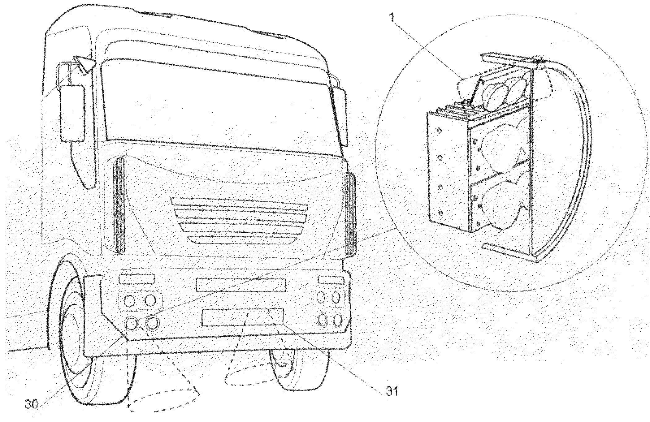
[0004]The object of the present invention is to provide an optical device for motor vehicles having a relatively simple and low-cost structure, which can be installed, for example, within a front light assembly or in other suitable points of a vehicle, for example, an automobile or a lorry, or an industrial vehicle in general, said device being able to recognize the condition of the road surface, and in particular being capable of discerning between the conditions of road dry, wet, icy, and covered with snow, supplying also, preferably, a corresponding value of the coefficient of friction that can be associated to the surface detected.
[0006]Thanks to the specified characteristics, the invention enables reliable information to be obtained with simple and of low-cost means, which enables discrimination not only between a dry condition and a wet condition of the road surface, but also, for example, between a wet condition and an icy condition or between an icy condition and a condition where the road surface is covered with snow. In particular, the invention is also able to supply, with simple and reliable means, information on the coefficient of friction that can be attributed to the road surface.

Problems solved by technology

However, with this methodology, even though it is relatively easy to distinguish between a condition of dry road and a condition of road that is not dry, the distinction between a wet condition and an icy condition proves to be more problematical.
The use of these methodologies is disadvantageous, above all for use on vehicles, on account of the high cost of the device.

Method used


Image

  • Optical device for motor vehicles, for detecting the condition of the road surface
  • Optical device for motor vehicles, for detecting the condition of the road surface
  • Optical device for motor vehicles, for detecting the condition of the road surface

Examples


Embodiment Construction

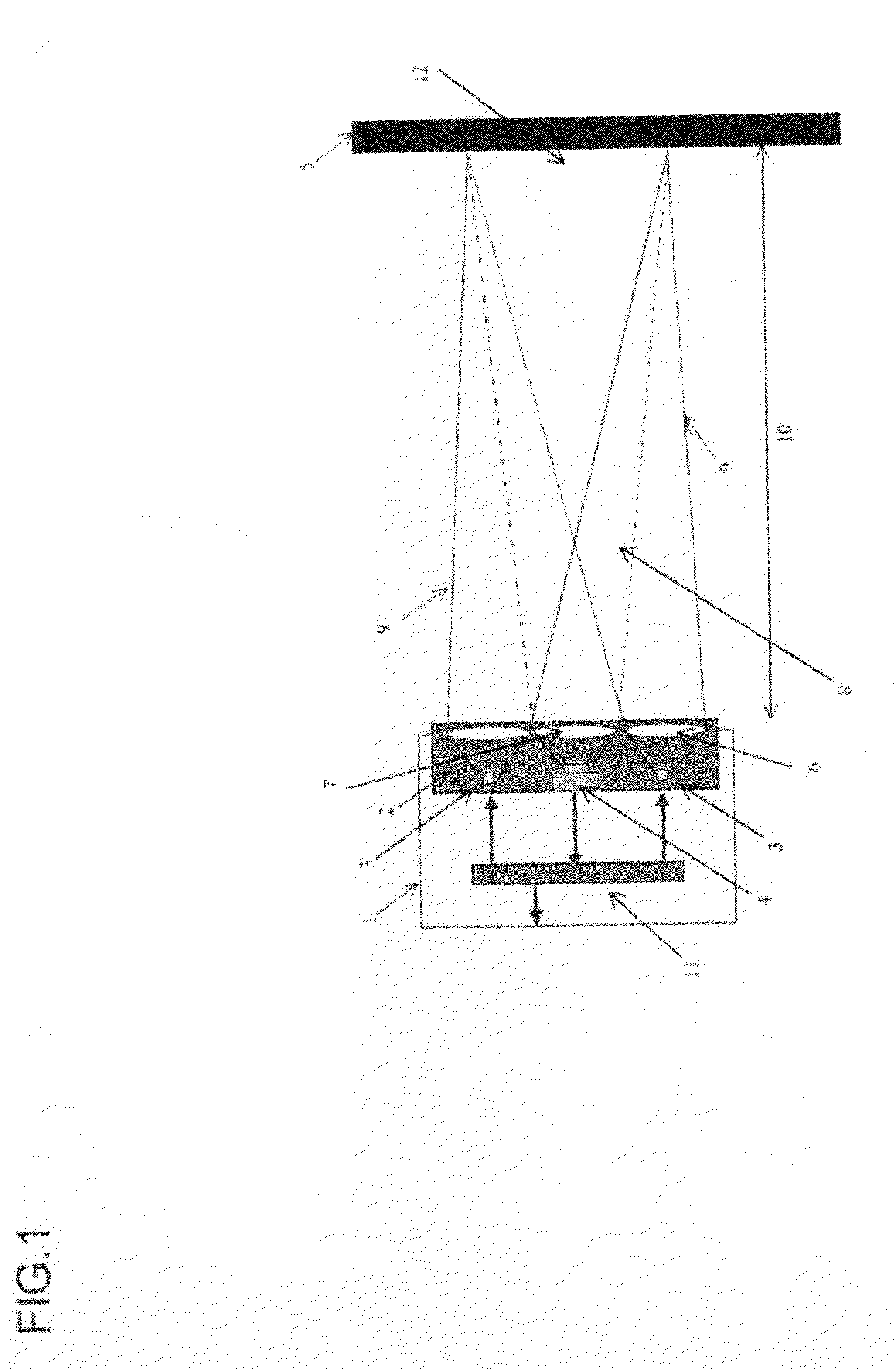
[0021]With reference to FIG. 1, the optical device 1 according to the invention comprises an optical unit 2, which includes a device for emission of radiation made up of at least two sources 3 that are able to emit radiation in the spectral region comprised in the visible and / or near infrared and of optical elements 6, such as lenses, fibres, etc., coupled to said sources 3 in such a way as to direct the radiation emitted by said sources onto a portion of road 12 with beams 9. Said beams are characterized in that, once the height of installation 10 of the device 1 from the road 5 has been established, the beams 9 superimpose on one another in a region 12 so as to light up said portion of road uniformly.

[0022]The device moreover includes a receiving unit 4, to which an optical element 7 is coupled, which is able to focus the radiation back-diffused by the portion of road 12 onto the receiving unit 4.

[0023]Described hereinafter is the principle of operation of the optical device accor...


PUM


Abstract

An optical device for motor vehicles, designed to detect the condition of the road surface, comprises a unit for the emission of electromagnetic radiation in the direction of the road surface to be detected, a receiving unit coupled to an optical element for focusing the radiation back-diffused by the road surface and an electronic control and processing unit for receiving signals at output from said receiving unit and for processing them in order to determine the condition of the road surface, on the basis of a reference map. Appearing in said map are the values of the intensity of radiation Iref back-reflected at a reference wavelength and at least one second wavelength. The map is divided into subareas identified beforehand as corresponding to the different conditions of the road surface.

Description

BACKGROUND OF THE INVENTION[0001]The present invention relates to optical devices that can be used on a motor vehicle for detection of the condition of the road surface, for example, for detecting whether the road surface is dry or wet and / or covered with snow and / or ice.[0002]Devices of this type are already known in the art. For instance, the U.S. Pat. No. 5,497,100 describes a device that makes use of an emitter of electromagnetic radiation having frequencies comprised in the spectral band of microwaves and which analyses the components of the radiation reflected from the road surface, distinguishing whether said surface is dry, wet, or icy, on the basis of the different dielectric constants between these conditions, which affect the reflected radiation.[0003]Other types of devices use the spectral band of the infrared, as described, for example, in the document DE-A-4008280. In this spectral range, in fact, there exist wavelengths that can be selectively absorbed by a wet or icy...

Claims


Application Information

Patent Timeline
Patent Type & Authority Applications(United States)
IPC IPC(8): H04N7/18G01J5/02G01J5/00
CPCB60W2420/40G01N21/3151G01N21/359B60W40/068G01N2201/0627G01N2201/0696B60Q1/0023G01N21/4738
Inventor CAPELLO, DAVIDEPALLARO, NEREOLIOTTI, LUCAGUGLIELMETTO, LUCA
Owner CENT RICERCHE FIAT SCPA
Learn More