
Bidirectional ESD Power Clamp

a power clamp and bidirectional technology, applied in the direction of resistors, emergency protective arrangements for limiting excess voltage/current, electrical appliances, etc., to achieve the effect of better control

Inactive Publication Date: 2010-06-10
INTERUNIVERSITAIR MICRO ELECTRONICS CENT (IMEC VZW)
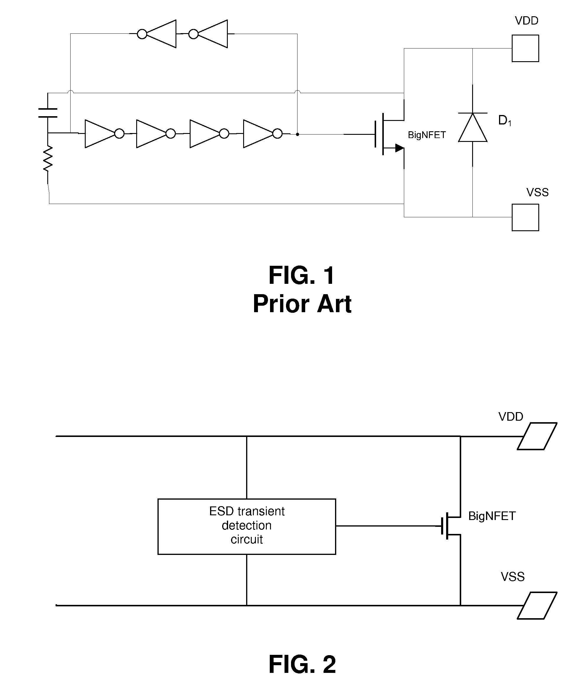
View PDF5 Cites 8 Cited by
  • Summary
  • Abstract
  • Description
  • Claims
  • Application Information

AI Technical Summary

Benefits of technology

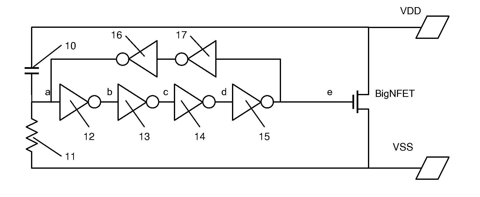
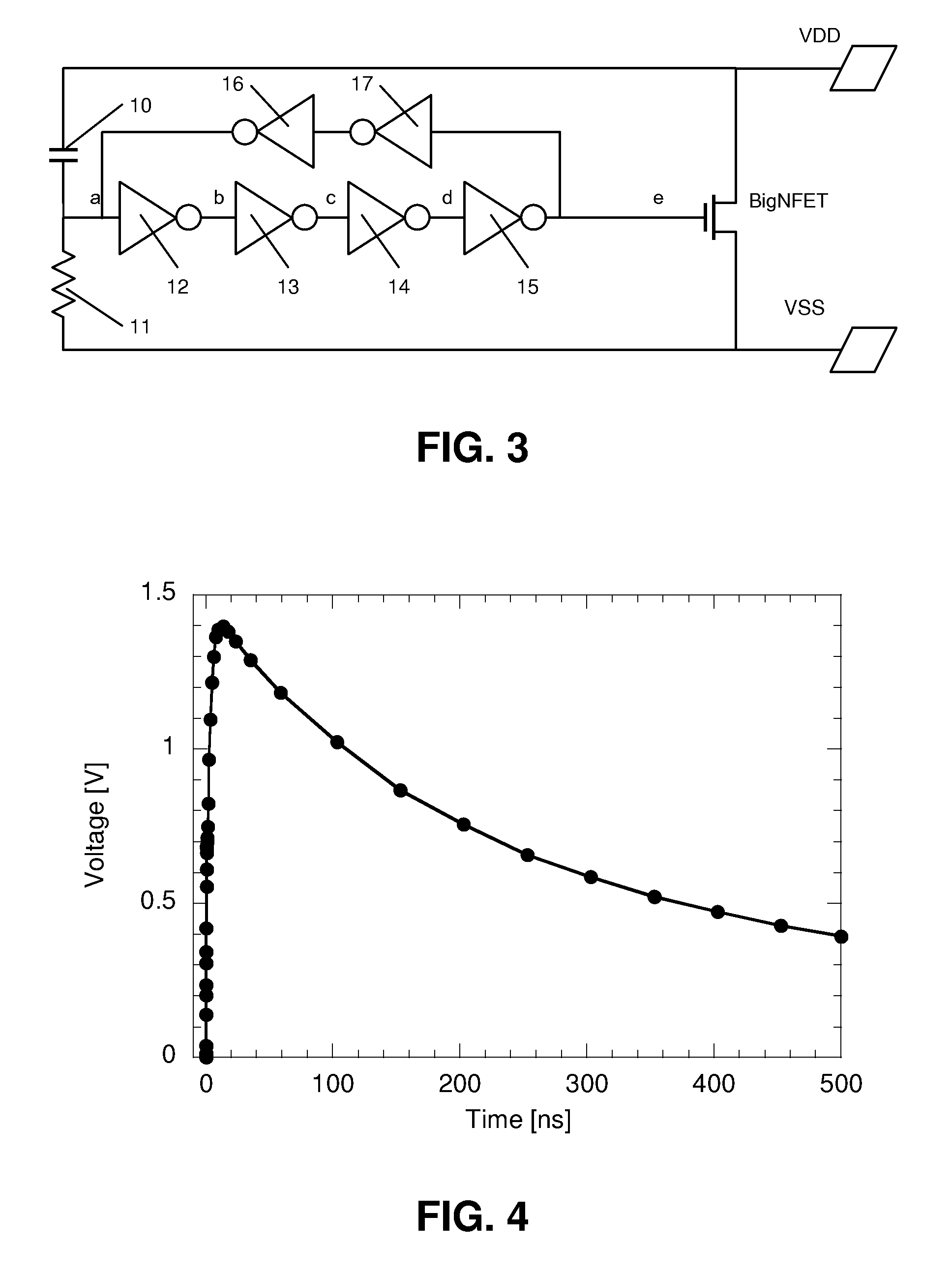
[0008]The invention is a bidirectional ESD power clamp for protecting a circuit against an ESD transient occurring between a first node and a second node of the circuit. The power clamp comprises a semiconductor structure having a conductive path connected between the first and second nodes and having a triggering node via which the conductive path can be triggered from a non-conducting state to a conducting state, said semiconductor structure being adapted for conducting ESD currents via the conductive path in a first direction from the first node to the second node while in said conducting state. The power clamp further comprises an ESD transient detection circuit connected between the first and second nodes and to the triggering node and comprising a first part for detecting occurrence of a first ESD transient on said first node and for triggering said semiconductor structure via said triggering node upon such detection of a first ESD transient. The power clamp according to the invention is characterised in that said semiconductor structure is provided on an insulator substrate, such that a parasitic conductive path between said first and second nodes via said substrate is avoided. Further, the semiconductor structure is adapted for conducting ESD currents via the conductive path in a second direction from the second node to the first node while in said conducting state. Further, the ESD transient detection circuit further comprises a second part for detecting occurrence of a second ESD transient on the second node and for triggering the semiconductor structure via said triggering node upon such detection of a second ESD transient.
[0009]In the ESD power clamp according to the invention, the ESD current can be conducted through the same conductive path in both directions as a result of the characterising features described above. Hence, the need for an additional current path for the reverse direction can be avoided and the device area consumed can be reduced.
[0013]In preferred embodiments, the second part of the ESD transient detecting circuit comprises at least one small transistor connected to said first node, said second node, and said triggering node such that it passes on a voltage on said second node as a result of said second ESD transient to said triggering node. This at least one small transistor has the advantage that the voltage on the triggering node upon occurrence of the second ESD event can be better controlled. With “small” is meant here that the transistor is sized to conduct bias currents (e.g. on the order of milli-ampere), as opposed to for example a large transistor which is sized to conduct much higher ESD currents (e.g. on the order of ampere).
[0014]In preferred embodiments, said ESD transient detection circuit further comprises a latch for maintaining said semiconductor structure in said conductive state for a longer time period. This has the advantage that the semiconductor structure is kept open for a longer time period for conducting the ESD current, avoiding that the ESD current is interrupted too soon. Preferably, the latch comprises an inverter chain with feedback inverters.
[0015]In preferred embodiments, the power clamp further comprises a second small transistor having a gate connected to the second node and a channel bridging part of said latch. This second small transistor has the advantage that the voltage on the triggering node upon occurrence of the second ESD event can be better controlled.

Problems solved by technology

This additional diode requires additional silicon area for the ESD protection, which is undesirable.

Method used


Image

  • Bidirectional ESD Power Clamp
  • Bidirectional ESD Power Clamp
  • Bidirectional ESD Power Clamp

Examples


Embodiment Construction

[0028]The present invention will be described with respect to particular embodiments and with reference to certain drawings but the invention is not limited thereto but only by the claims. The drawings described are only schematic and are non-limiting. In the drawings, the size of some of the elements may be exaggerated and not drawn on scale for illustrative purposes. The dimensions and the relative dimensions do not necessarily correspond to actual reductions to practice of the invention.

[0029]Furthermore, the terms first, second, third and the like in the description and in the claims, are used for distinguishing between similar elements and not necessarily for describing a sequential or chronological order. The terms are interchangeable under appropriate circumstances and the embodiments of the invention can operate in other sequences than described or illustrated herein.

[0030]Moreover, the terms top, bottom, over, under and the like in the description and the claims are used fo...


PUM


Abstract

The disclosed method and device relates to a bidirectional ESD power clamp, comprising a semiconductor structure (BigNFET; BigPFET) having a conductive path connected between first and second nodes and having a triggering node via which the conductive path can be triggered. An ESD transient detection circuit is connected between the first and second nodes and to the triggering node and comprises a first part for detecting an occurrence of a first ESD transient on the first node. The semiconductor structure is provided on an insulator substrate, such that a parasitic conductive path between said first and second nodes via the substrate is avoided. The ESD transient detection circuit further comprises a second part for detecting an occurrence of a second ESD transient on the second node.

Description

CROSS-REFERENCE TO RELATED APPLICATIONS[0001]The present application claims priority to European Patent Application EP 08170702.8 filed in the EPO Patent Office on Dec. 4, 2008, the entire contents of which is incorporated herein by reference.BACKGROUND[0002]1. Field of the Invention[0003]The present invention relates to an ESD power clamp according to the preamble of the first claim.[0004]2. Description of the Related Art[0005]In general RC-triggered power clamps are not bidirectional ESD devices on their own. Additional ESD devices need to be added in order to deliver bi-directional operation. Commonly a reverse diode will provide an additional current path. This additional diode requires additional silicon area for the ESD protection, which is undesirable.SUMMARY[0006]It is an aim of the present invention to provide a bidirectional ESD power clamp which consumes less area.[0007]This aim is achieved according to the invention with an ESD power clamp showing the technical character...

Claims


Application Information

Patent Timeline
IPC IPC(8): H02H9/04
CPCH01L27/0285
Inventor LINTEN, DIMITRITHIJS, STEVENTREMOUILLES, DAVID ERICIYER, NATARAJAN MAHADEVA
Owner INTERUNIVERSITAIR MICRO ELECTRONICS CENT (IMEC VZW)
Learn More