Illumination system

a technology of illumination system and illumination system, which is applied in the direction of instruments, non-linear optics, lighting and heating apparatus, etc., can solve the problems of insufficient output light requirements of available light-emitting devices, inconvenient operation, and insufficient light output of illumination system, so as to achieve uniform intensity and color output

Active Publication Date: 2010-06-10
SIGNIFY HLDG BV
View PDF8 Cites 54 Cited by
  • Summary
  • Abstract
  • Description
  • Claims
  • Application Information

AI Technical Summary

Benefits of technology

[0008]It is an object of the invention to provide an illumination system which provides a more uniform intensity and color output.

Problems solved by technology

In some of these applications, such as a backlight for use in an LCD display, the requirements on the light output of the illumination system may be quite strict, and available light-emitting devices may not meet these requirements sufficiently.
An additional problem is that the optical characteristics of the associated object may vary—for example, LCD panels may be produced using different techniques and different materials by different manufacturers—which means that the output light requirements on the associated illumination system must also vary.
In other words, one illumination system, for example, one backlight, may not be suitable for the whole range of associated objects even when luminescent elements are used.
However, a drawback of the known illumination system with the phosphor on the cover plate is that variation in phosphor layer thickness causes spatial intensity and color variations in the light emitted by the phosphor.
Such variations are noticeable by the user of the LCD panel and considered undesirable.

Method used


Image

  • Illumination system
  • Illumination system
  • Illumination system

Examples


Embodiment Construction

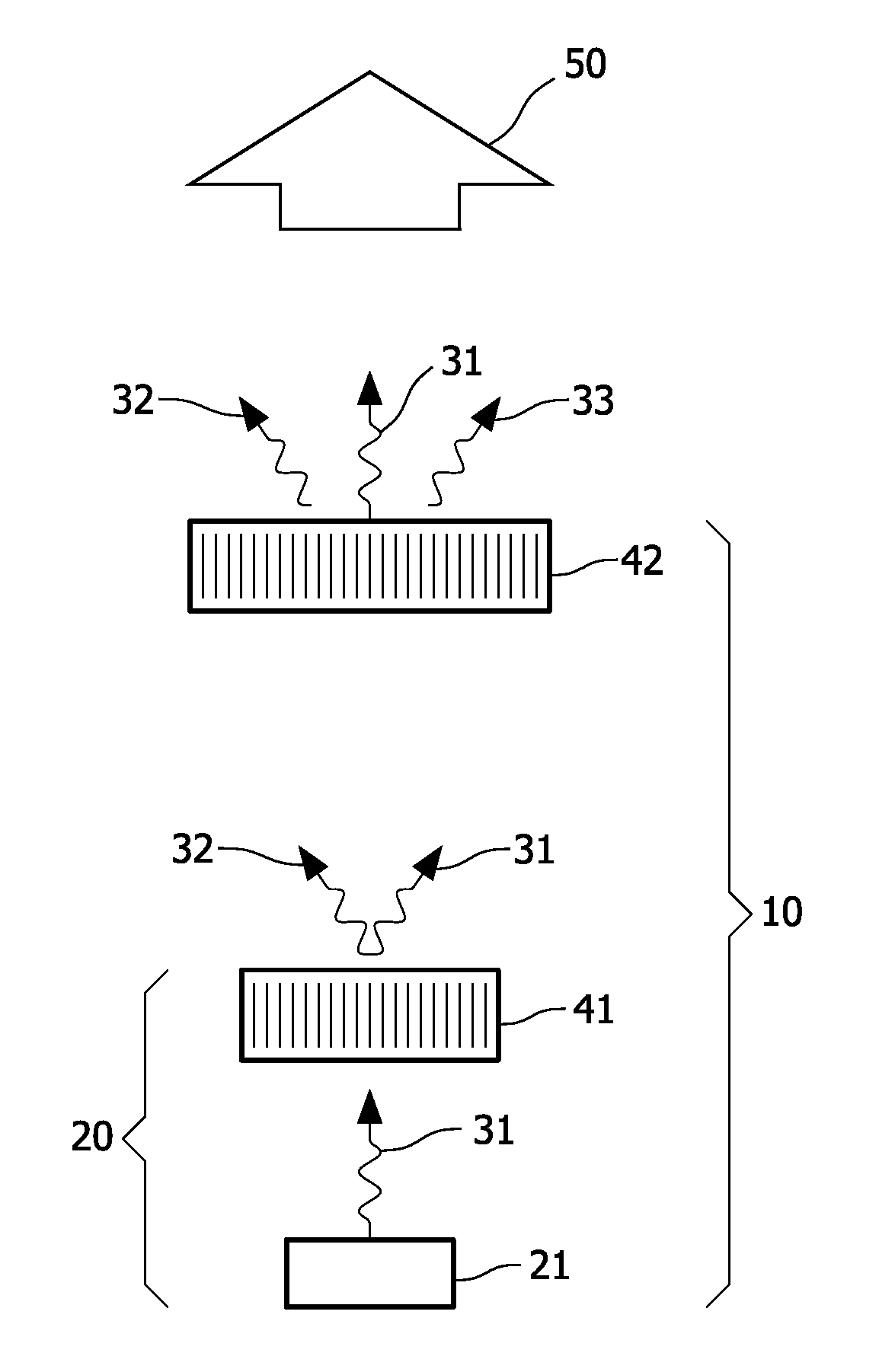
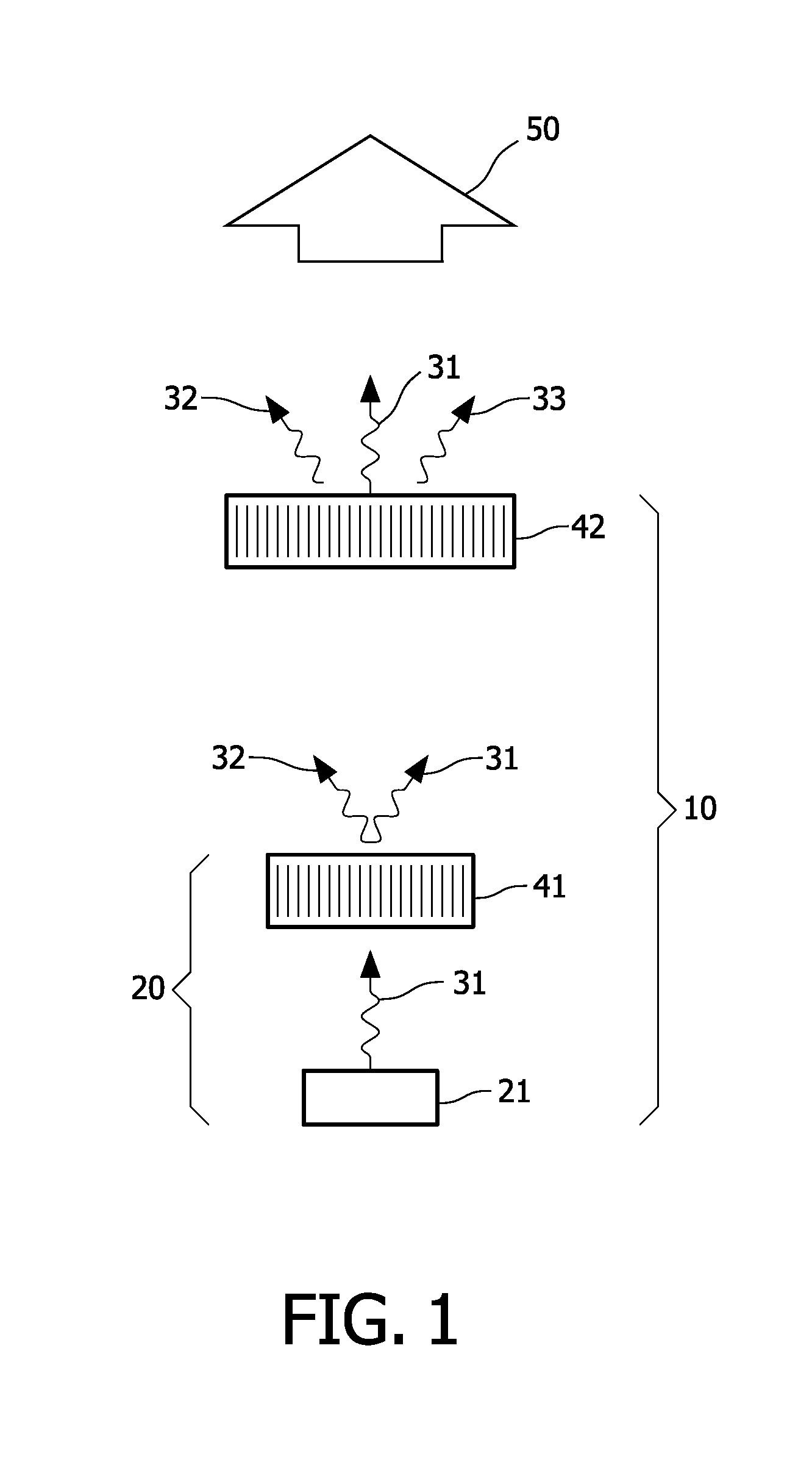
[0056]FIG. 1 shows a schematic cross-sectional view of illumination system 10 according to the invention. The illumination system 10 comprises a semiconductor light-emitting device 20 which emits Blue light 31 in the direction of a first phosphor layer 41. Typically, it is the chip or die 21 of the light-emitting device 20 which emits the light. The first phosphor layer 41, which forms part of the semiconductor light-emitting device 20 and is thus physically very close to the source of Blue light, is arranged to intercept at least some of the Blue light, and the phosphor material is selected to absorb the Blue light 31 and to emit a first Yellow light 32 due to the excitation by the Blue light 31. Due to its proximity to the Blue light source, the first phosphor layer 41 may be referred to as a “local” phosphor layer.

[0057]Phosphor materials suitable for use in the first phosphor layer 41 include garnet phosphors. Garnet phosphors have the following general formula:

(Y1-x-y-a-bLUxGdy...


PUM


Abstract

The invention provides an illumination system comprising a light-emitting device which excites a first luminescent element, which forms part of the light-emitting device. The light emitted from the first luminescent element and/or the light emitted by the light-emitting device excite a second luminescent element, physically separated from the light-emitting device. By employing two luminescent elements, the first element in the light-emitting device, and the second element physically separated from the light-emitting device, such as on a cover plate, the conversion of light produced by the light-emitting device is performed at both a “local” and a “remote” location, respectively, and the amount of luminescent material required at the remote location may be reduced compared to the situation of the prior art where the light conversion was only performed at a remote location.

Description

FIELD OF THE INVENTION[0001]The invention relates to illumination systems.[0002]The invention also relates to a display device comprising an illumination system.BACKGROUND OF THE INVENTION[0003]Illumination systems are known per se and are used to provide light in both functional applications and decorative applications. In functional applications, such as street lamps, ceiling- and wall-mounted lighting fixtures, the light is typically provided to counteract reduced visibility and the light output is therefore configured accordingly. The requirements on the light output may include parameters such as wavelength spectrum, color point or color temperature, intensity, solid angle, light area, luminous power, luminance etc. Generally, the wavelength spectrum relates to the color of the light. In illumination applications such as general lighting or product highlighting, the color rendering properties of the light generally is an important requirement on the light output, which relates ...

Claims


Application Information

Patent Timeline
Patent Type & Authority Applications(United States)
IPC IPC(8): F21V9/16F21V9/00H01L33/50
CPCG02F1/133603H01L33/507G02F2001/133614G02F1/133614
Inventor VAN WOUDENBERG, ROELHOELEN, CHRISTOPH GERARD AUGUST
Owner SIGNIFY HLDG BV
Why Eureka
Try Eureka