Grow-light system

a technology of grow lights and light tubes, which is applied in the direction of lighting and heating apparatus, semiconductor devices for light sources, lighting support devices, etc., can solve the problems of not being well suited to provide vertical light canopies for grow beds, light systems are not satisfactory, etc., and achieve the effect of reducing the die-off of light density and/or light intensity

Inactive Publication Date: 2022-05-05
DEMEGROW INC
View PDF6 Cites 0 Cited by
  • Summary
  • Abstract
  • Description
  • Claims
  • Application Information

AI Technical Summary

Benefits of technology

[0014]In accordance with a preferred embodiment of the invention, the grow-light canopy provides substantially uniform light density and / or light intensity over the a central illumination area of a grow bed by reducing the light density and / or light intensity die-off at outer edges of the light canopy. Light density refers to a summation of photons emitted of all wavelengths over an area, and light intensity refers to a number of photons emitted for a selected wavelength over the area; light density and light intensity can, in some cases, be used interchangeably. Luminous flux (in lumens) is a measure of the total amount of light output in all directions, while luminous intensity (in candelas) is a measure of beam brightness in a particular direction. This application is generally concerned with luminous intensity of light that reaches a grow bed positioned below a grow-light canopy. However, it is understood that for unfocused light, luminous flux and luminous intensity are generally proportional to each other.
[0015]To reduce die-off of light density and / or light intensity at outer edges of a grow-light canopy, the present invention utilizes LED light bars with spatially modulated LED configurations. For example, LEDs, or arrays of LEDs, are spaced or positioned along the light emitting surfaces such that distances between adjacent LEDs, or arrays of LEDs, are sequentially reduced, when moving from the center portion of the light emitting surface of a LED light bar to the two end portions of the light emitting surfaces of the LED light bar.

Problems solved by technology

This solution however is not satisfactory because of the increased footprint and inefficient energy consumption of the grow-light system.
Currently available LED grow-light systems, are also not well suited for providing vertical light canopies for vertical grow beds.

Method used


Image

  • Grow-light system
  • Grow-light system
  • Grow-light system

Examples


Embodiment Construction

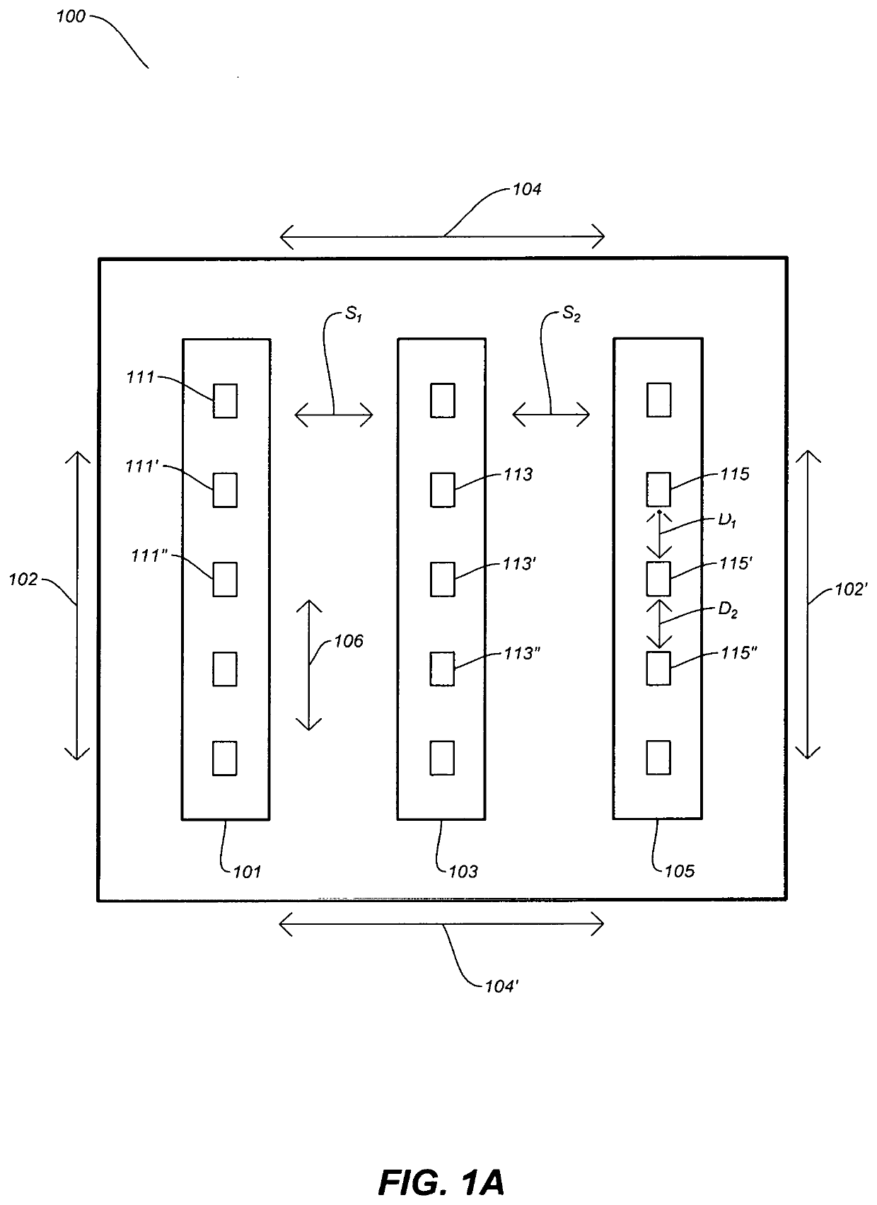
[0043]Referring to FIG. 1A, a LED grow-light system can include a LED grow-light canopy 100 with any number of LED light bars 101, 103 and 105. The LED light bars 101, 103 and 105 are preferably linear elongated LED light bars that are arranged to be parallel with respect to each other in a parallel or elongated direction, as indicated by the arrow 106.

[0044]Each of the LED light bars 101, 103 and 105 include LEDs or arrays of LEDs 111 / 111′ / 111″, 113 / 113′ / 113″, and 115 / 115′ / 115″, respectively. The separation between adjacent and sequential LEDs or arrays of LEDs 111 / 111′ / 111″, 113 / 113′ / 113″, and 115 / 115′ / 115″ is uniform, as indicated by the arrow D1 and D2. Also, the parallel separations of distances between adjacent LED light bars is also usually uniform, as indicated by the arrow S1 and S2. The light canopy 100 described and illustrated in FIG. 1A will exhibit die off in light density, and / or intensity, around the outside edges 102 / 102′ and 104 / 104′ of the LED grow-light canopy 10...


PUM

PropertyMeasurementUnit
areaaaaaaaaaaa
light spectrumaaaaaaaaaa
spectrumaaaaaaaaaa

Abstract

A LED grow-light system is disclosed. The LED grow-light system includes one or more grow-light canopies with linear LED light bars to provide upward and downward lighting in a central illumination area. The LED light bars are preferably configured to move up and down relative to a grow bed. The LED grow-light system or grow-light canopies constructed using T-slot interconnects that lock into T-channels of the T-slot bars and / or T-slot light bars.

Description

RELATED APPLICATION[0001]This U.S. patent application is a continuation application of the co-pending U.S. patent application Ser. No. 17 / 300,225, filed Apr. 14, 2021, and titled “LED GROW-LIGHT SYSTEM”, which is a continuation-in-part of co-pending U.S. patent application Ser. No. 16 / 501,984, filed on Jul. 15, 2019, now U.S. Pat. No. 10,999,980, and titled “DUAL-LAYER LED GROW-LIGHT SYSTEM”, which is a continuation-in-part of co-pending U.S. patent application Ser. No. 16 / 501,389, now abandoned, filed on Apr. 3, 2019, and titled “LED GROW-LIGHT SYSTEM” which claims priority under 35 U.S.C. § 119(e) from the U.S. provisional patent application Ser. No. 62 / 761,710, filed on Apr. 3, 2018, and titled “LED-GROW LIGHT SYSTEM.” This U.S. patent application is also a continuation-in-part of co-pending U.S. patent application Ser. No. 17 / 300,050, filed on Feb. 16, 2021 titled “T-SLOT BAR INTERCONNECT SYSTEM”, which claims priority under 35 U.S.C. § 119(e) from the U.S. provisional patent ap...

Claims


Application Information

Patent Timeline
Patent Type & Authority Applications(United States)
IPC IPC(8): A01G7/04A01G9/24F21S4/28F21V21/15
CPCA01G7/045A01G9/249F21Y2103/10F21V21/15F21S4/28F21Y2115/10F21Y2105/12F21S2/00
Inventor GOETTLE, BLANE J.GRAHAM, JESSE JAMESMUSGROVE, MICHAEL DARREN
Owner DEMEGROW INC
Why Eureka
Try Eureka