Method and device for generating uniform high-frequency plasma over large surface area used for plasma chemical vapor deposition apparatus

a technology of high-frequency plasma and chemical vapor deposition apparatus, which is applied in the direction of chemical vapor deposition coating, plasma technique, coating, etc., can solve the problems of large surface area film forming difficulty, unstable plasma itself, and non-uniformity in plasma distribution, so as to reduce power loss, increase the range, and rapid self-cleaning

Inactive Publication Date: 2007-04-17
MITSUBISHI HEAVY IND LTD
View PDF16 Cites 38 Cited by
  • Summary
  • Abstract
  • Description
  • Claims
  • Application Information

AI Technical Summary

Benefits of technology

[0022]Thus, by alternating cycles of the high frequency power being supplied at the same frequency, and being supplied at different frequencies, when the high frequency waves are supplied to the discharge electrode at the same frequency, the waves coming from both sides resonate in the middle to increase the plasma density in that area, but on the other hand, when the waves from both sides of the electrode are of different frequencies, they tend to cancel each other out at the center to lower the plasma density in that area. Thus when alternating these cycles and looking at the average over time, the generation of the plasma is such that the standing wave distribution is uniform over the large surface area above the discharge electrode, which results in a uniform thickness of deposition on the large surface area substrate, as well as uniform self-cleaning.
[0029]Thus, the time ratio between the first cycle and second cycle may be varied according to the gas pressure and type of gas; for example, using an identical duty cycle, different gas conditions could cause the state of plasma generation to differ. However, such a situation could be handled and a uniform plasma density could be achieved in this manner without requiring any hardware changes.
[0035]The application of the direct current bias to the power supply section of the discharge electrode makes it possible to reduce the sheath capacitance of the discharge electrode, which increases the wavelength of the standing wave to uniformize the plasma density.
[0036]Further still in this invention, an axial direction of power supply cables to the first and second power supply sections may be matched to the axial direction of the discharge electrode to minimize the current return distances, and reduce the power loss from the power source, to thereby increase range over which the plasma is generated.
[0038]By matching the axial direction of the power source cable to the power supply section to the axial direction of the discharge electrode, the power from the power source can smoothly enter the discharge electrode, and the minimization of the current return distance reduces the power losses to increase the range over which plasma is generated.
[0039]Additionally, the present invention is characterized by the configuration, in which gas may be delivered that readily forms plasma to the inside of the plasma chemical vapor deposition apparatus being within a range to satisfy the conditions required for rapid film forming by plasma chemical vapor deposition and rapid self-cleaning of the plasma chemical vapor deposition apparatus.

Problems solved by technology

One problem with these very high frequency film forming methods is the difficulty of obtaining uniformity in large surface area film forming.
Since the wavelength of these very high frequencies is on the same order as the electrode size, a standing wave is generated at the ends of the electrodes due to reflected waves causing a floating inductance capacitance that affects the voltage distribution, which in turn causes nonuniformity in the plasma distribution due to the interference between the plasma and the high frequency waves.
Further, the NF3 plasma used in self-cleaning, being a negatively charged gas (electrons adhere easily), causes the plasma itself to be very unstable, and in addition its distribution is nonuniform due to the gas flow (the plasma being generated on the downstream side) and differences in the distance between electrodes.
Thus, when the frequency exceeds 30 MHz, the above described effects become pronounced and it is difficult to achieve even the minimal uniformity in film thickness of ±10% for manufacturing the semiconductor film.
However, in this case as well, it becomes difficult to form uniform films when the electrode size exceeds 30 cm or when the frequency exceeds 80 MHz.
However, this method does not fundamentally eliminate standing waves, but merely generates the flat part of a sine wave over the electrode, which produces a uniform area which is approximately ⅛ of that wavelength.
In theory, further uniformization beyond that range would not be possible.
Thus, the conventional technology for plasma chemical vapor deposition apparatus that perform very high frequency plasma generation could not generate plasma to produce a uniform film upon very large substrates that exceed 1 m×1 m in size.

Method used


Image

  • Method and device for generating uniform high-frequency plasma over large surface area used for plasma chemical vapor deposition apparatus
  • Method and device for generating uniform high-frequency plasma over large surface area used for plasma chemical vapor deposition apparatus
  • Method and device for generating uniform high-frequency plasma over large surface area used for plasma chemical vapor deposition apparatus

Examples


Embodiment Construction

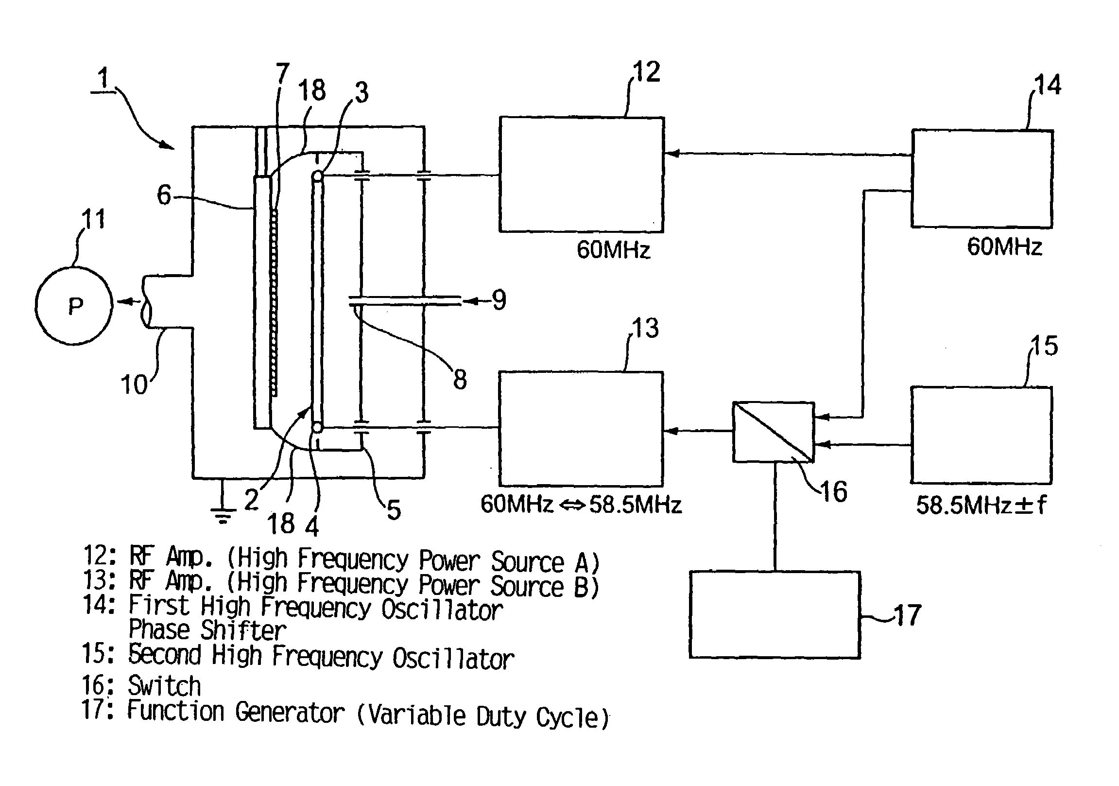
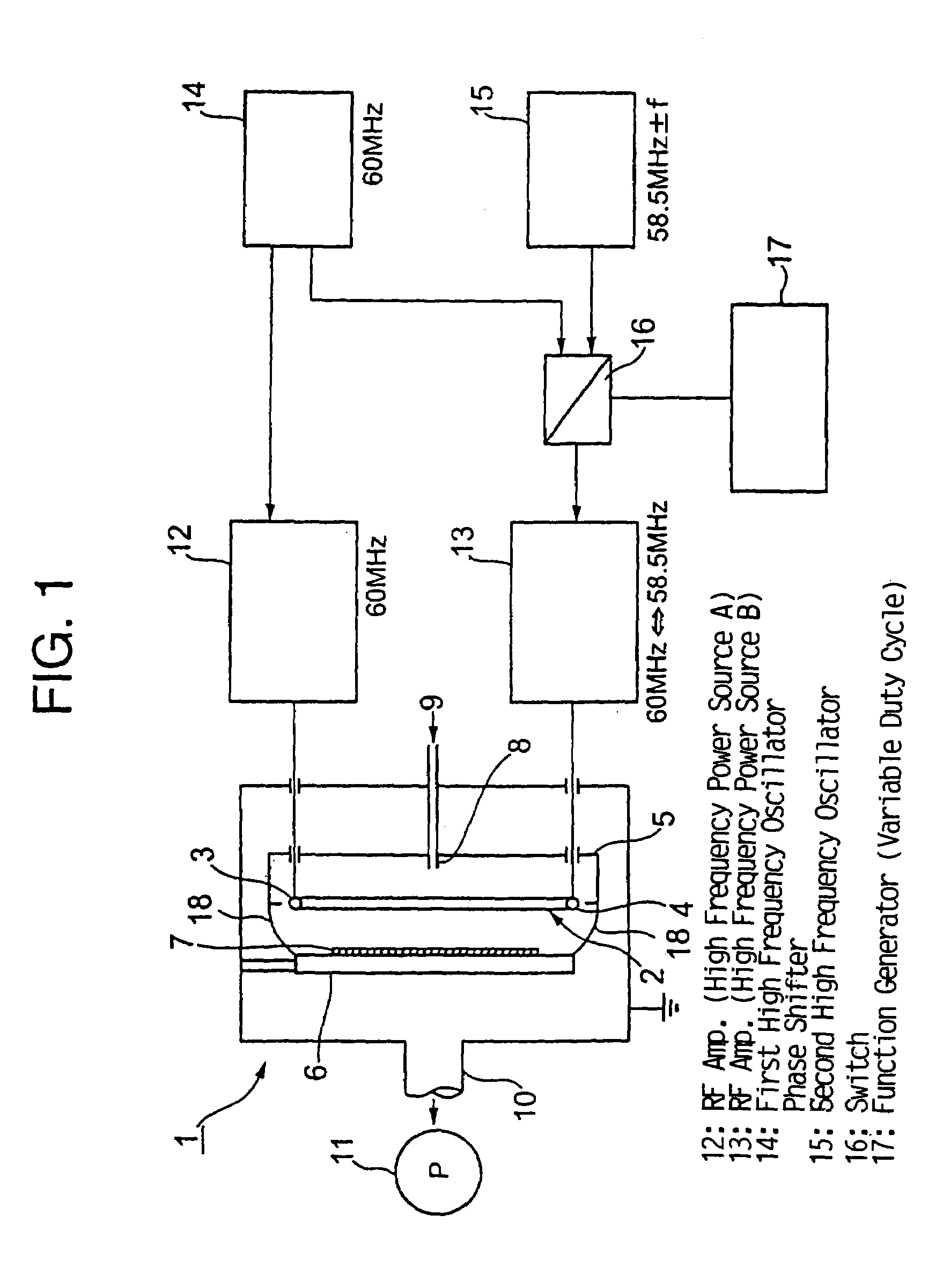
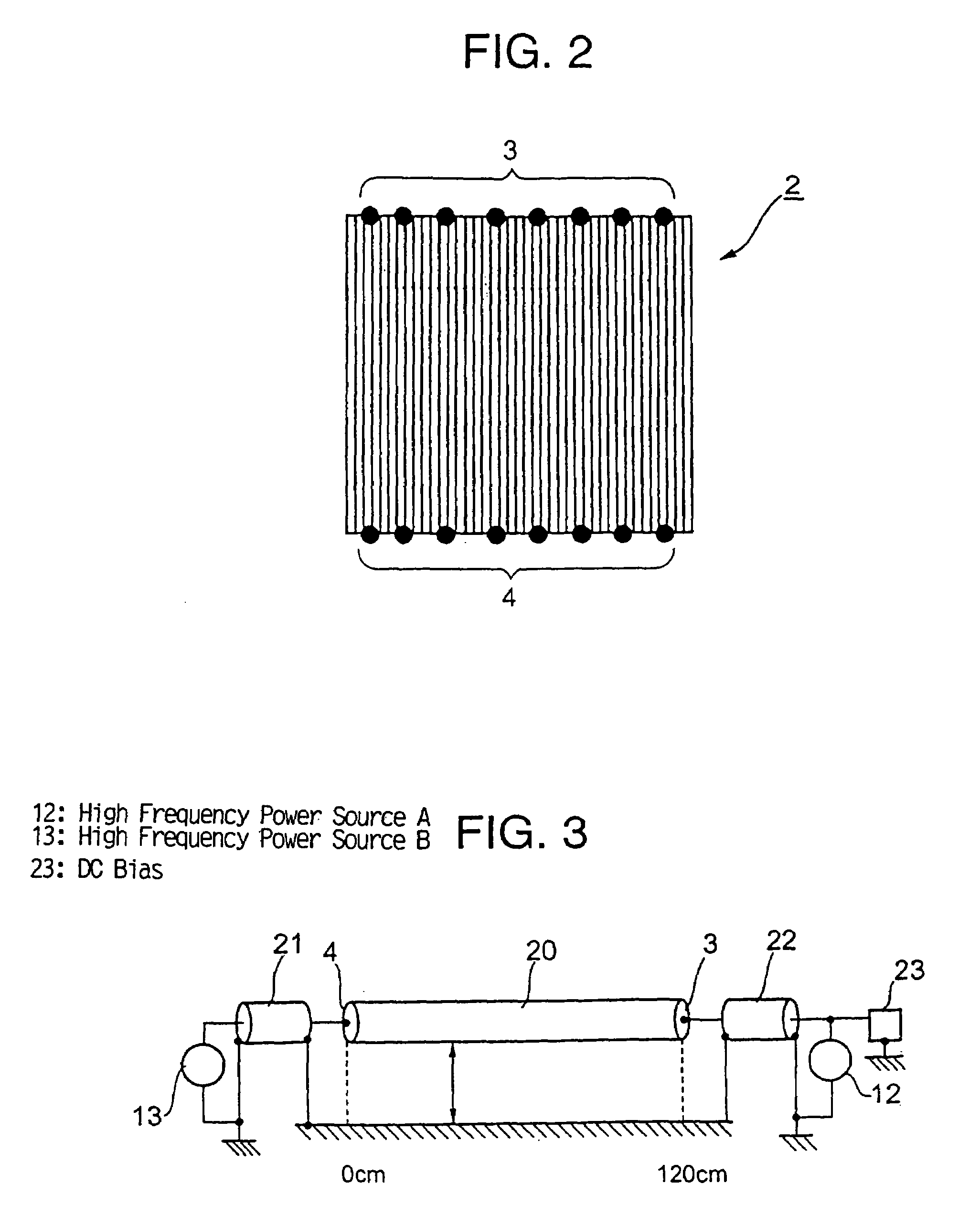
[0049]The basic configuration of this invention provides for a plasma chemical vapor deposition apparatus of the class that can accommodate an electrode size of 1.5 m×1.2 m, a gas pressure of 12 to 20 Pa (90–150 mTorr) while utilizing a high frequency power source of 60 MHz. As was described above in section on means used to resolve problems with the existing technology, a first and a second power supply section are established on each end of the discharge electrode in the plasma chemical vapor deposition apparatus; these are powered alternately with high frequency waves in two cycles, a cycle in which the same frequency of high frequency is supplied, and a cycle in which different frequencies of high frequency power are supplied. When viewed over time, the plasma generation, in other words, the standing wave distribution over the discharge electrode, is uniform over the large surface area by the different plasma generation in each cycle. Further, in this present invention, the foll...


PUM

PropertyMeasurementUnit
temperatureaaaaaaaaaa
pressureaaaaaaaaaa
distanceaaaaaaaaaa

Abstract

A plasma generation device for generating plasma uniformly over a large surface area by very high frequency (VHF), which is installed in a plasma chemical vapor deposition apparatus. A first and a second power supply section are installed on both ends of the discharge electrode installed in a plasma chemical vapor deposition apparatus, and are supplied with alternate cycles: the first cycle wherein the first and second power supply sections receive high frequency waves at the same frequency, and a second cycle wherein different high frequency waves are received. In this manner, the state of plasma generation may be varied in each cycle, and when averaged over time, it makes possible uniform plasma generation over a large surface area.

Description

FIELD OF THE INVENTION[0001]The present invention relates to a method and device for generating uniform high-frequency plasma over a large surface area used for a plasma chemical vapor deposition apparatus. The plasma chemical vapor deposition apparatus is used for forming or etching the semiconductor films from amorphous silicon, microcrystal silicon, multicrystal thin films silicon, silicon nitride, etc. for use in solar cells, thin film transistors or the like, and used for performing fluorine radical cleaning (self-cleaning) which cleans the amorphous silicon (a-Si) deposits inside the film-forming chamber using NF3 gas plasma.TECHNICAL BACKGROUND[0002]A high frequency plasma generator device used in a plasma chemical vapor deposition apparatus performs forming or etching the semiconductor films from amorphous silicon (hereinafter abbreviated “a-Si”), microcrystal silicon, multicrystal thin films silicon, silicon nitride, etc. for use in solar cells, thin film transistors or the...

Claims


Application Information

Patent Timeline
Patent Type & Authority Patents(United States)
IPC IPC(8): H05H1/24C23C16/509H01J37/32
CPCC23C16/509H01J37/32082H01J37/32174
Inventor KAWAMURA, KEISUKETAKANO, AKEMIMASHIMA, HIROSHITAKATUKA, HIROMUYAMAUTI, YASUHIROTAKEUCHI, YOSHIAKISASAKAWA, EISHIRO
Owner MITSUBISHI HEAVY IND LTD
Why Eureka
Try Eureka