Plasma processing device, plasma processing method and method of manufacturing element including substrate to be processed

a processing device and plasma technology, applied in the direction of plasma technique, chemical vapor deposition coating, coating, etc., can solve the problems of disadvantageous non-uniform plasma and difficult to reduce the size of the device, and achieve the effect of high processing speed

Active Publication Date: 2011-12-22
CANON ANELVA CORP
View PDF2 Cites 42 Cited by
  • Summary
  • Abstract
  • Description
  • Claims
  • Application Information

AI Technical Summary

Benefits of technology

[0022]According to the present invention, there is provided a method of manufacturing an element including a substrate to be processed, the method including: a step of arranging the substrate to be processed on a substrate holder provided within a vacuum vessel for performing predetermined plasma processing; a step of generating a plasma within the vacuum vessel; and a step of forming a separatrix expanding from an upper wall to the substrate holder by a magnetic field line generated by applying a current to a first magnetic field generation means that is provided on the upper wall of the vacuum vessel opposite the substrate holder and that can adjust a generated magnetic field by an applied current and a magnetic field line generated by a second magnetic field generation means provided on a side wall of the vacuum vessel, and of performing the predetermined plasma processing, wherein, the step of performing the plasma processing can adjust the shape of the se

Problems solved by technology

However, in the device disclosed in patent document 1, in order to make the generated plasma diffuse and become uniform, it is necessary for charged particles generated by the plasma to fly a longer distance within the coil magnetic field as the substrate to be processed becomes larger, and thus it is disadvantageous

Method used


Image

  • Plasma processing device, plasma processing method and method of manufacturing element including substrate to be processed
  • Plasma processing device, plasma processing method and method of manufacturing element including substrate to be processed
  • Plasma processing device, plasma processing method and method of manufacturing element including substrate to be processed

Examples


first embodiment

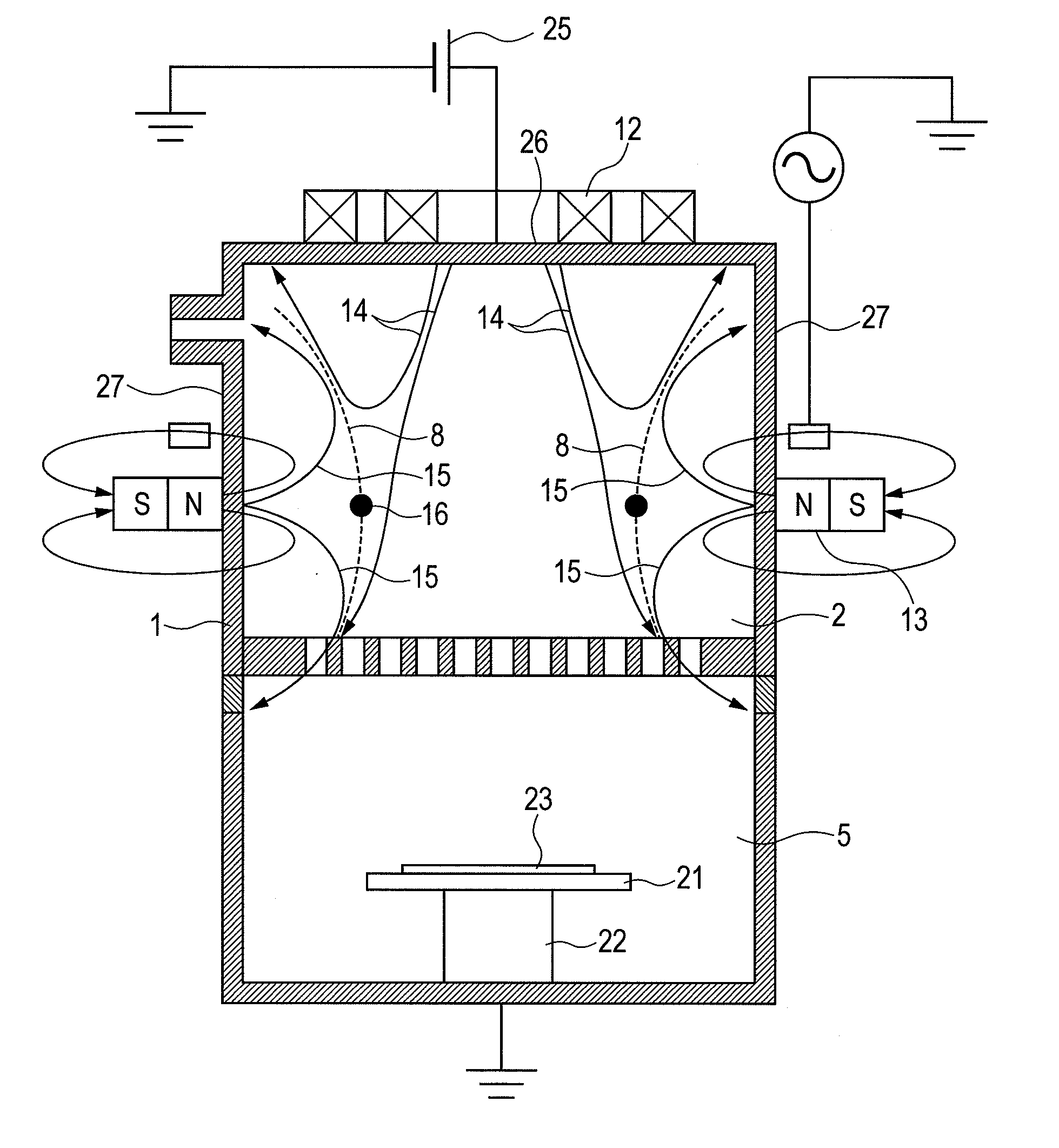
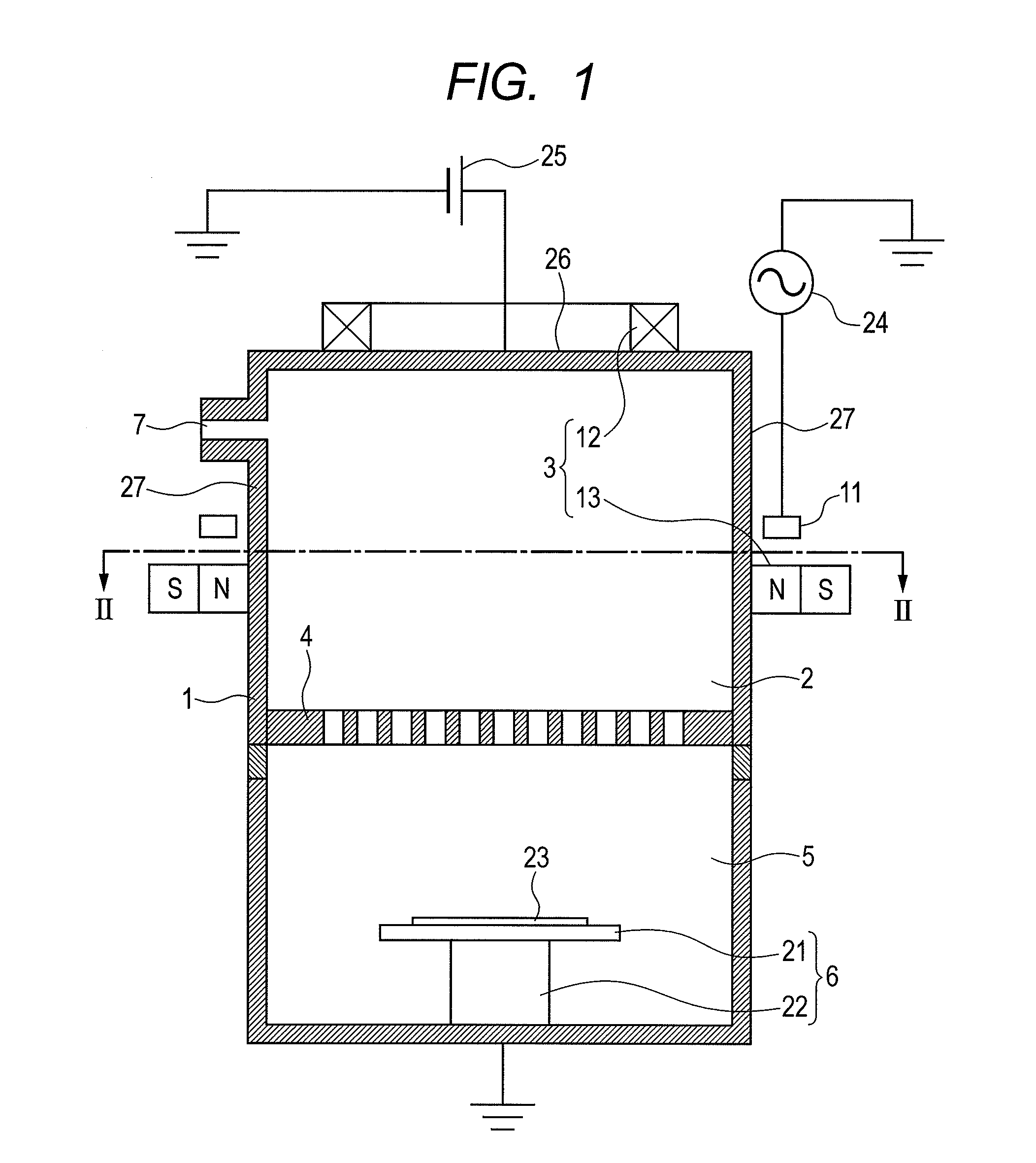
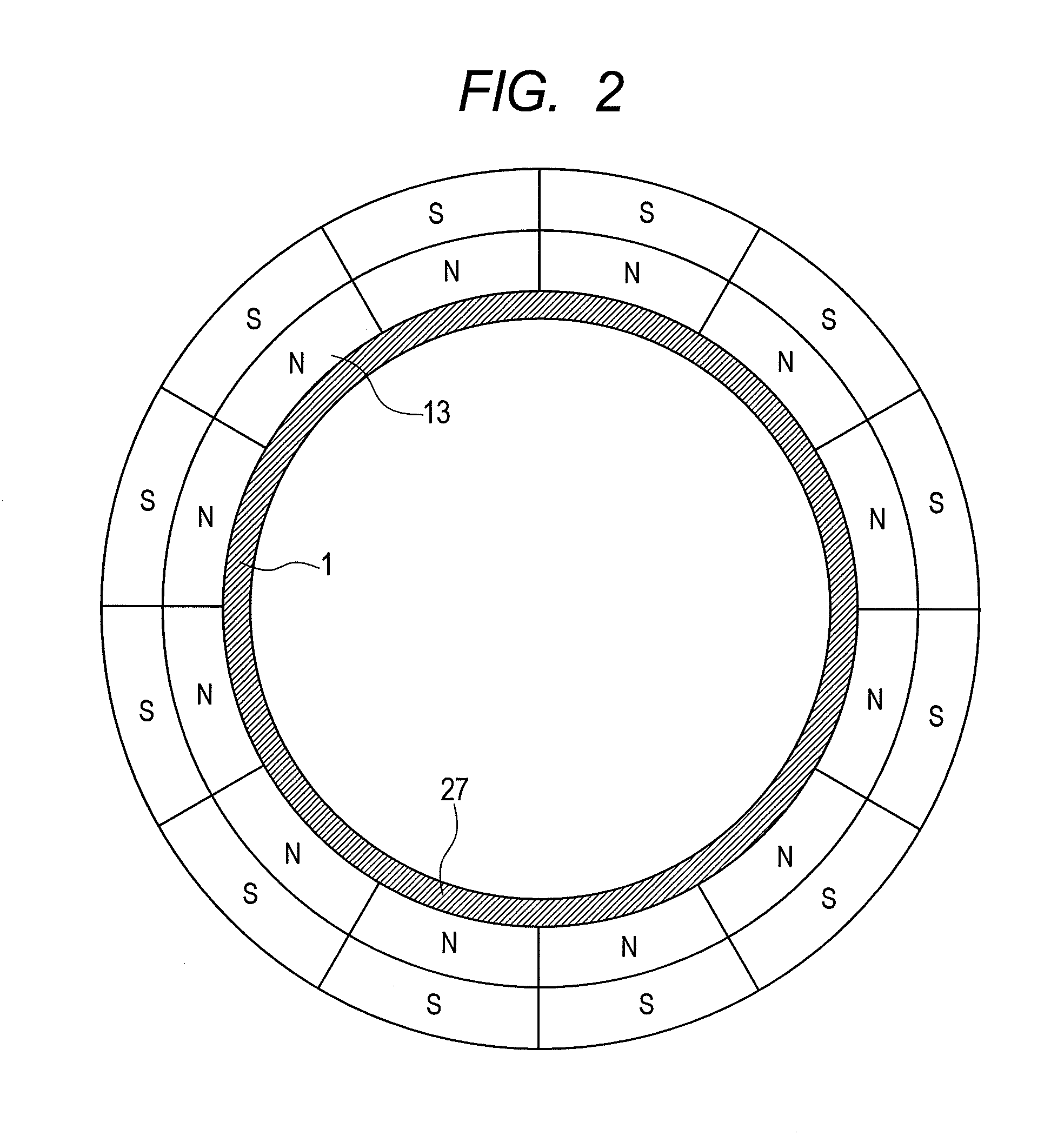
[0042]FIG. 1 is a cross-sectional view schematically showing the configuration of an inductively-coupled plasma processing device that is a preferred embodiment of a plasma generation device according to the present invention; FIG. 2 is a cross-sectional view taken along line II-II of FIG. 1; and FIG. 3 is a diagram showing the distribution of magnetic field lines generated in the device of the present embodiment.

[0043]In the plasma processing device of FIG. 1, a vacuum vessel 1 is divided by a bulkhead plate (grid) 4, which has communication holes, into a plasma generation chamber 2 and a plasma processing chamber 5. The plasma generation chamber 2 includes a plasma generation mechanism such as an SLA (single loop antenna) 11 and a magnetic circuit 3 having magnetic coils 12 and permanent magnets 13, and the magnetic circuit 3 generates a magnetic field within the vacuum vessel 1. The plasma processing chamber 5 includes a substrate holding mechanism 6. The vacuum vessel 1 includes...

second embodiment

[0108]Although, in the first embodiment, the magnetic circuit 3 includes the magnetic coils 12 arranged on the upper wall 26 such that the north pole points to the inside of the vacuum vessel 1 and the south pole points to the outside of the vacuum vessel 1 and the permanent magnets 13 arranged on the side wall 27 such that the north pole points to the inside of the vacuum vessel 1 and the south pole points to the outside of the vacuum vessel 1, in the present embodiment, the configuration of the magnetic circuit 3 is not limited to this configuration.

[0109]In the present invention, as long as the magnetic circuit 3 in which the magnetic coils 12 are arranged on the side (the upper wall 26) of the vacuum vessel 1 opposite the substrate holder 21 is used and thus it is possible to form the separatrices 8 expanding from the opposite side toward the substrate holder 21, the magnetic circuit 3 may be freely configured.

[0110]For example, in the configuration shown in FIG. 1, the directio...


PUM

PropertyMeasurementUnit
Magnetic fieldaaaaaaaaaa
Densityaaaaaaaaaa
Currentaaaaaaaaaa

Abstract

The present invention provides a plasma processing device and a plasma processing method that can easily adjust plasma density distribution while making the plasma density uniform, and a method of manufacturing an element including a substrate to be processed. In an embodiment of the present invention, the inside of a vacuum vessel (1) is divided by a grid (4) having communication holes into a plasma generation chamber (2) and a plasma processing chamber (5). On the upper wall (26) of the plasma generation chamber (2), magnetic coils (12) are arranged such that magnetic field lines within the vacuum vessel (1) point from the center of the vacuum vessel (1) to a side wall (27), and, outside the side wall (27) of the plasma generation chamber (2), ring-shaped permanent magnets (13) are arranged such that a polarity pointing to the inside of the vacuum vessel (1) is a north pole and a polarity pointing to the outside of the vacuum vessel (1) is a south pole.

Description

CROSS-REFERENCES TO RELATED APPLICATIONS[0001]This application is a continuation application of International Application No. PCT / JP2010 / 051134, filed Jan. 28, 2010, which claims the benefit of Japanese Patent Application No. 2009-025852, filed Feb. 6, 2009. The contents of the aforementioned applications are incorporated herein by reference in their entities.TECHNICAL FIELD[0002]The present invention relates to a plasma processing device, a plasma processing method and a method of manufacturing an element including a substrate to be processed. More particularly, the present invention relates to a plasma processing device and a plasma processing method that process a substrate with a plasma such as by utilizing the plasma to form a thin film on the surface of the substrate to be processed or etching the surface of the substrate to be processed, and a method of manufacturing an element including a substrate to be processed.Background Art[0003]Conventionally, for example, in etching d...

Claims


Application Information

Patent Timeline
IPC IPC(8): C23F1/00C23F1/08H05H1/24C23C16/50
CPCH01J37/32357H01J37/32422H05H2001/4667H01L43/12H05H1/46H01J37/3266H05H1/4652H10N50/01H01L21/205H01L21/3065H01L21/31
Inventor IORI, KAZUYUKINAKAGAWA, YUKITO
Owner CANON ANELVA CORP
Why Eureka
Try Eureka