Projector with preferred lighting uniformity

a projector and lighting technology, applied in the field of projectors, can solve the problem that the projection picture of the conventional laser projector cannot provide preferred color uniformity, and achieve the effect of uniform intensity

Active Publication Date: 2022-01-06
QUISDA CORP
View PDF1 Cites 0 Cited by
  • Summary
  • Abstract
  • Description
  • Claims
  • Application Information

AI Technical Summary

Benefits of technology

The present invention allows for the flexible adjustment of the number of solid-state light sources in a projector based on the illumination demand. It utilizes an alignment module to position the polarization lens, reflector, and phase retarder to transform the polarized state of the illumination beam emitted by the illumination modules. The phase retarder can be one half wave plate or a combination of two quarter wave plates. The invention also allows for the adjustment of the arrangement of the alignment module to prevent uneven intensity in the projection image caused by mechanical error. The invention provides a uniform intensity and color distribution for the projection image.

Problems solved by technology

In the conventional laser projector, the illumination beam and the excitation beam are difficult to well mix, and a projection picture of the conventional laser projector cannot provide preferred color uniformity.

Method used


Image

  • Projector with preferred lighting uniformity
  • Projector with preferred lighting uniformity
  • Projector with preferred lighting uniformity

Examples


first embodiment

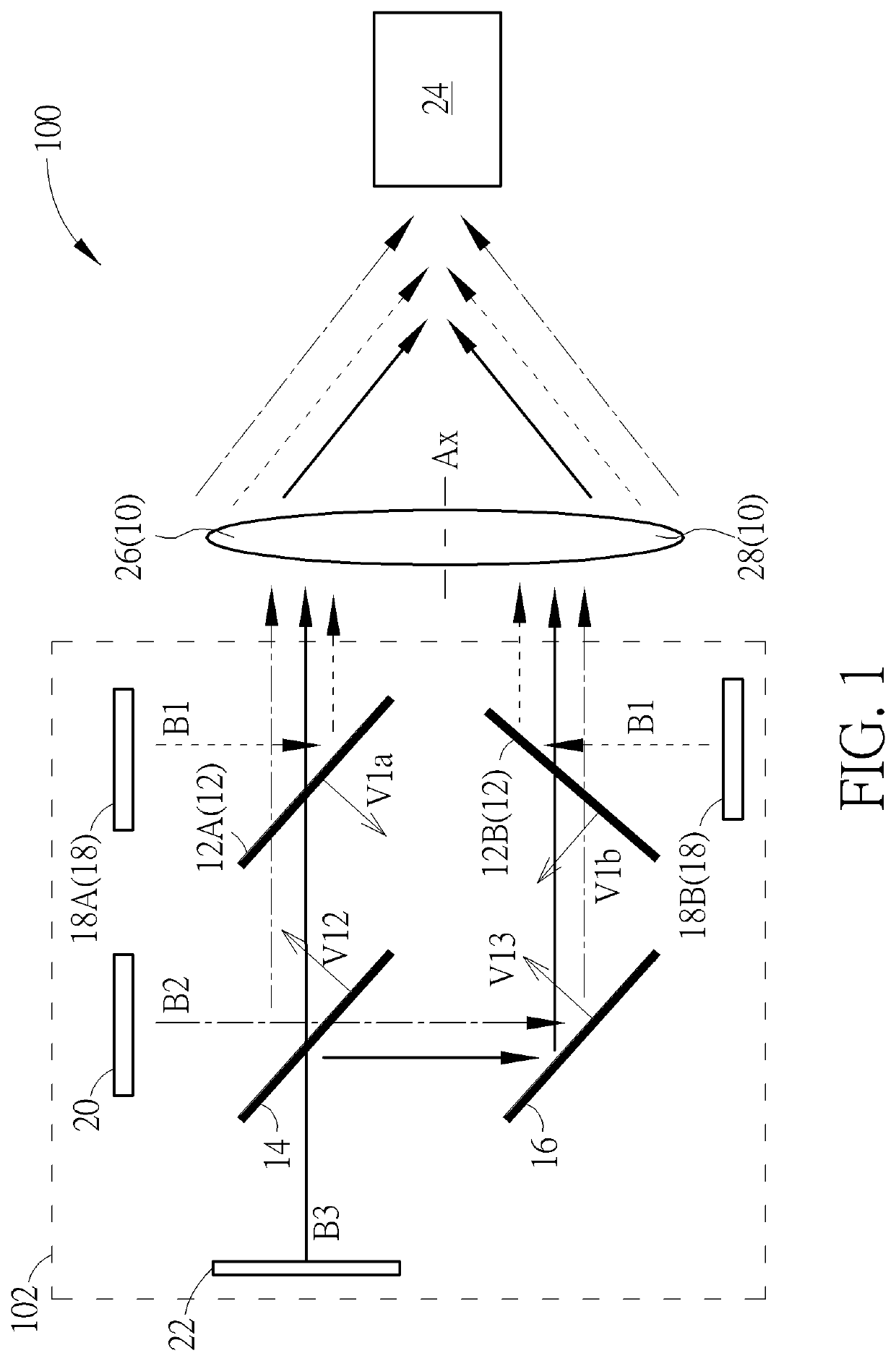
[0018]The projector 100 in the first embodiment may include two first solid-state light sources 18, such as the first solid-state light source 18A and the first solid-state light source 18B respectively corresponding to the first dichroic lens 12A and the first dichroic lens 12B. The second solid-state light source 20 can be disposed on a side of the second dichroic lens 14 different from the light transmission component 16. The third second solid-state light source 22 can be disposed on the other side of the second dichroic lens 14 different from the first part 26 of the collimator lens 10; that is to say, the collimator lens 10 can be set on the right side of the second dichroic lens 14, and the second solid-state light source 20 can be set on the upper side of the second dichroic lens 14, and the light transmission component 16 can be set on the lower side of the second dichroic lens 14, and the third solid-state light source 22 can be set on the left side of the second dichroic ...

second embodiment

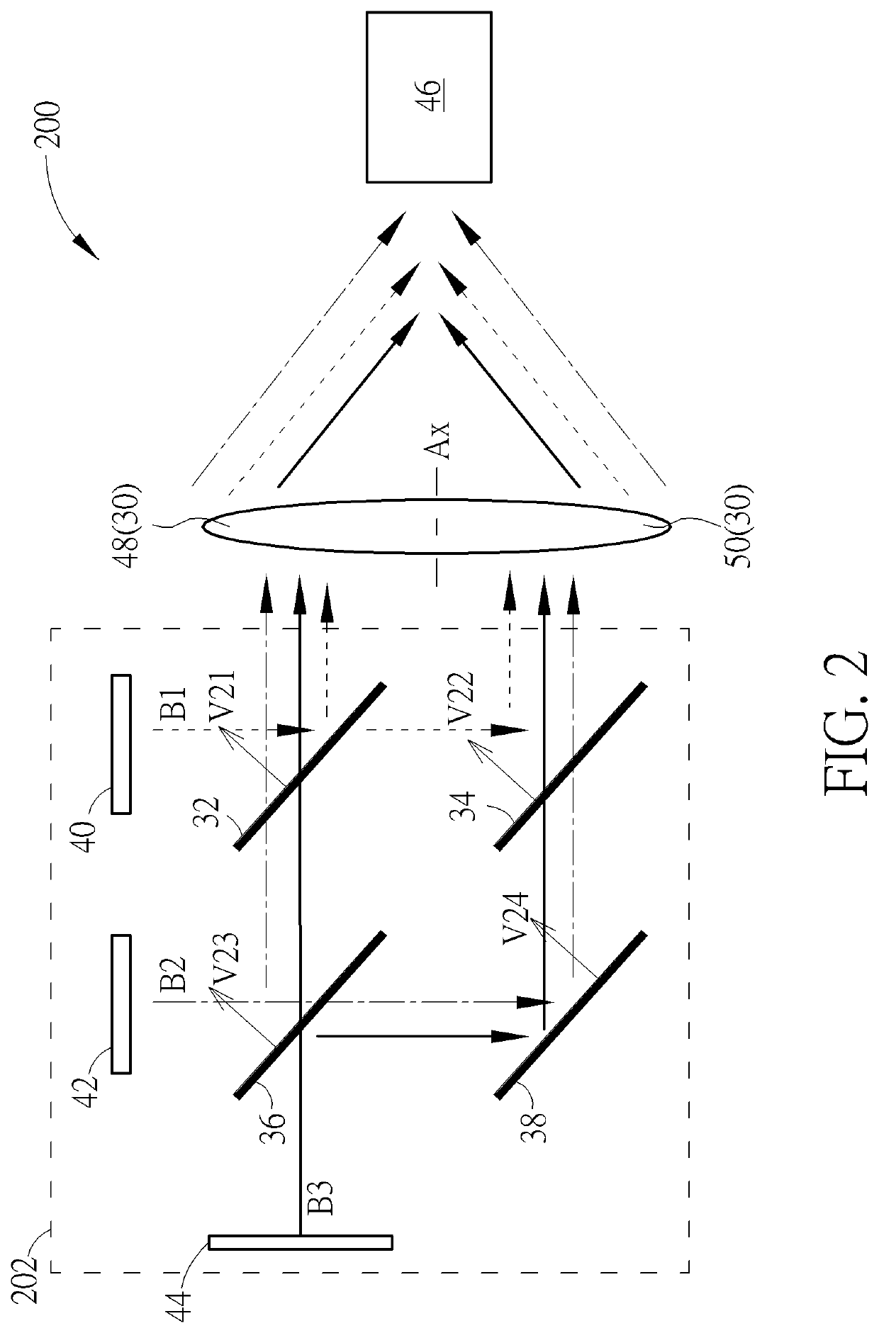
[0023]Please refer to FIG. 2. FIG. 2 is a diagram of a projector 200 according to the present invention. The projector 200 can include a collimator lens 30, a first dichroic lens 32, a second dichroic lens 34, a third dichroic lens 36, a light transmission component 38, a first solid-state light source 40, a second solid-state light source 42, a third second solid-state light source 44 and an optical receiver 46. The collimator lens 30 can include a first part 48 and a second part 50 divided by the axle Ax. The first dichroic lens 32 can correspond to the first part 48 of the collimator lens 30. The second dichroic lens 34 can correspond to the first dichroic lens 32 and the second part 50 of the collimator lens 30. The third dichroic lens 36 can be disposed on a side of the first dichroic lens 32 different from the collimator lens 30, and further correspond to the first part 48 of the collimator lens 30. The light transmission component 38 can correspond to the second dichroic lens...

third embodiment

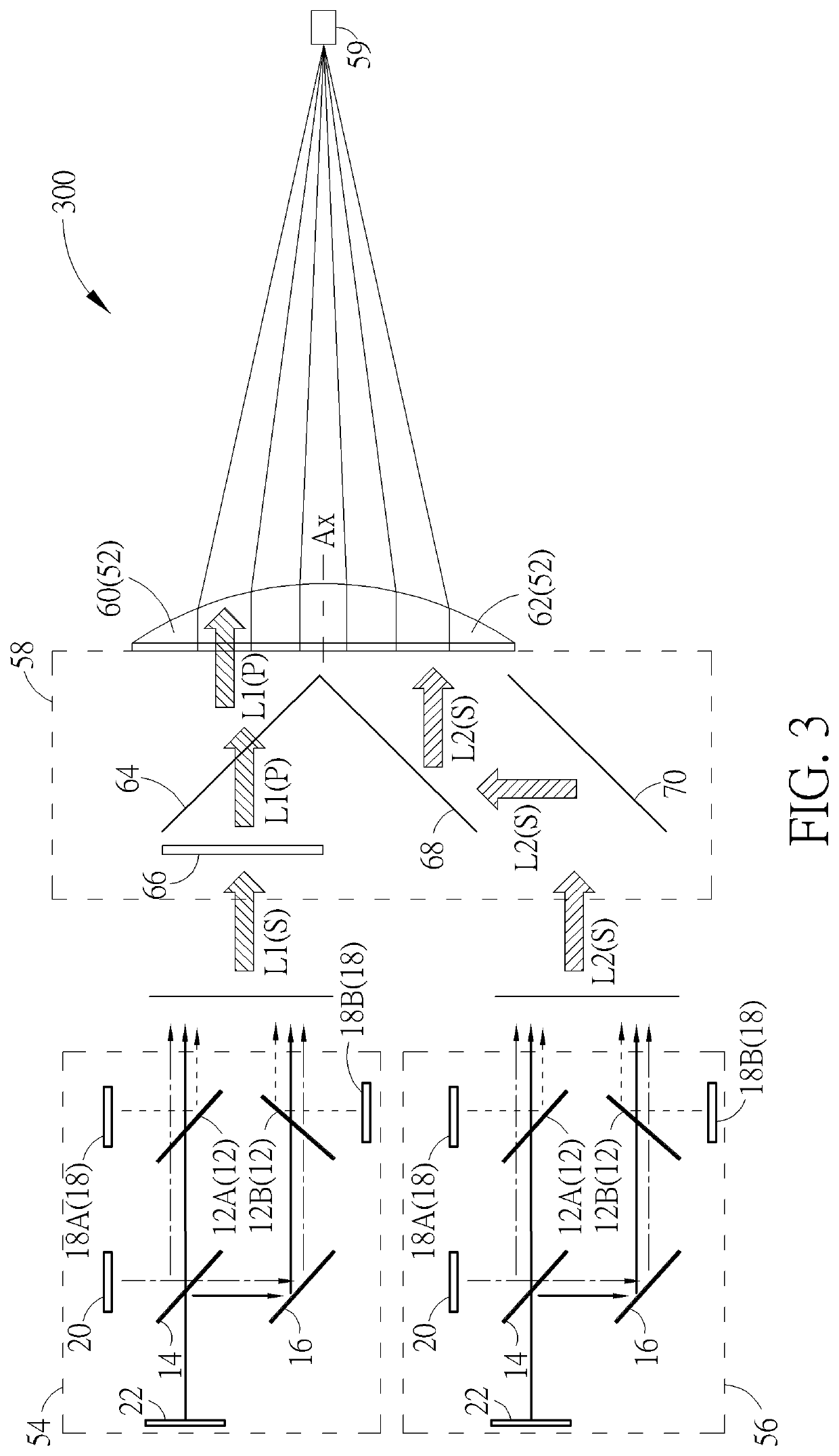
[0031]In the third embodiment, the first illumination module 54 can emit the first illumination beam L1 with the first polarized state S toward the first phase retarder 66, and the first phase retarder 66 can transform the first illumination beam L1 into the second polarized state P and project toward the first polarization lens 64; the first illumination beam L1 with the second polarized state P can pass through the first polarization lens 64 and then through the first part 60 of the collimator lens 52. Further, the second illumination module 56 can emit the second illumination beam L2 with the first polarized state S toward the second polarization lens 70, and the second polarization lens 70 can reflect the second illumination beam L2 toward the first reflector 68, and the first reflector 68 can reflect the second illumination beam L2 with the first polarized state S to pass through the second part 62 of the collimator lens 52. The optical receiver 59 can correspond to the collima...


PUM

PropertyMeasurementUnit
included angleaaaaaaaaaa

Abstract

A projector includes a collimator lens, a, a light transmission component and a solid-state light source. Amounts of the dichroic lens and the solid-state light source are plural. The dichroic lens and the light transmission component reflect beams with specific wavelength, and allow passing of beams with other wavelength. The solid-state light source emits the beams to the corresponding dichroic lens. The projector utilizes the dichroic lens and the light transmission component to pass the beams with different base color uniformly through the first part and the second part of the collimator lens. The projector further includes a polarized lens, a reflection lens and a phase retardation unit. The phase retardation unit transforms polarization of the beams, and the polarized lens reflects some polarized beams and allows passing of other polarized beams to combine a plurality of alignment modules for providing uniform illumination.

Description

BACKGROUND OF THE INVENTION1. Field of the Invention[0001]The present invention relates to a projector, and more particularly, to a projector with preferred lighting uniformity.2. Description of the Prior Art[0002]The conventional laser projector utilizes the blue light laser source to provide the illumination beam. The illumination beam is transformed into an excitation beam with different color via the wavelength conversion device (such as the color wheel partly covered by phosphor powder or quantum dot material); then, the excitation beam is mixed with the illumination beam for related application. The conventional alignment module utilizes the dichroic component to reflect the illumination beam toward the color wheel via a part of the collimator lens. A portion of the color wheel made by wavelength conversion material generates the excitation beam accordingly, and the excitation beam is directly projected onto the light receiver via the collimator lens. Besides, a part of the il...

Claims


Application Information

Patent Timeline
Patent Type & Authority Applications(United States)
IPC IPC(8): G03B33/12G03B21/20
CPCG03B33/12G03B21/208G03B21/2066G03B21/2013G03B21/2073G03B21/206G03B21/2053G03B33/06
Inventor CHIEN, CHIH-SHIUNGLIN, MING-KUENWU, TSUNG-HSUN
Owner QUISDA CORP
Why Eureka
Try Eureka