Apparatus and Method for Generating Directional Sound

a technology of directional sound and apparatus, applied in the field of sound processing technology, can solve the problems of limiting the movement of the listener, impairing the listener's ability to hear other sound, and affecting the directivity of the output sound, so as to achieve the effect of improving the directivity of sound and maintaining directivity

Inactive Publication Date: 2010-06-10
SAMSUNG ELECTRONICS CO LTD
View PDF17 Cites 26 Cited by
  • Summary
  • Abstract
  • Description
  • Claims
  • Application Information

AI Technical Summary

Benefits of technology

[0010]Accordingly, according to one general aspect, there is provided an apparatus and method for generating directional sound that improves directivity of sound by synthesizing output sound signals of an internal loudspeaker array and an edge loudspeaker cluster to remove output in side directions while maintaining directivity in a sound output direction.
[0016]Each of the edge loudspeakers may include a sound transducer to output sound waves having opposite phases forward and backward, a reflective plate located at a rear of the sound transducer, and a first blocking plate provided between a front portion and a rear portion of the sound transducer to increase an interference distance between a forward radiation sound from the sound transducer and a backward radiation sound of the sound transducer obtained where a sound wave output from the sound transducer is reflected by the reflective plate.
[0017]Each of the edge loudspeakers may further include a second blocking plate connected to the reflective plate and provided to cover an area on top of the sound transducer and / or an area at bottom of the sound transducer, to reduce directivity of sound waves output from the sound transducer in a vertical direction.

Problems solved by technology

Accordingly, the output sound may act as a disruption when delivered to a person who does not wish to hear it.
Although the use of headphones or earphones may enable the output sound to be delivered to a specific listener, these may limit a movement of the listener and may even impair the listener's ability to hear other sound.
However, assuming the size of a specific sound zone is proportional to a wavelength of the sound, the size of the sound generating apparatus in such a method may need to increase.
Also, the cost of the sound generating apparatus may increase as the apparatus likely need a plurality of sound sources having good efficiency in all frequency bands.
However, this may not improve directivity of the sound and merely increase the quality of sound in a low-frequency band.

Method used


Image

  • Apparatus and Method for Generating Directional Sound
  • Apparatus and Method for Generating Directional Sound
  • Apparatus and Method for Generating Directional Sound

Examples


Embodiment Construction

[0035]The following detailed description is provided to assist the reader in gaining a comprehensive understanding of the methods, apparatuses, and / or systems described herein. Accordingly, various changes, modifications, and equivalents of the systems, apparatuses and / or methods described herein will be suggested to those of ordinary skill in the art. Also, descriptions of well-known functions and constructions may be omitted for increased clarity and conciseness.

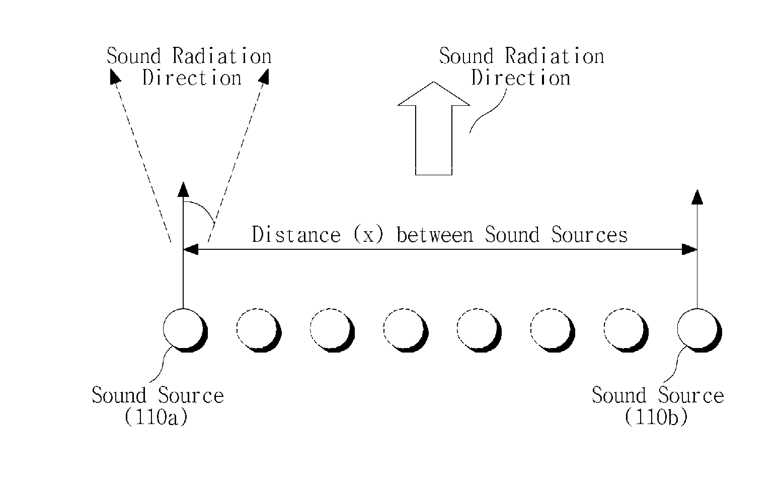
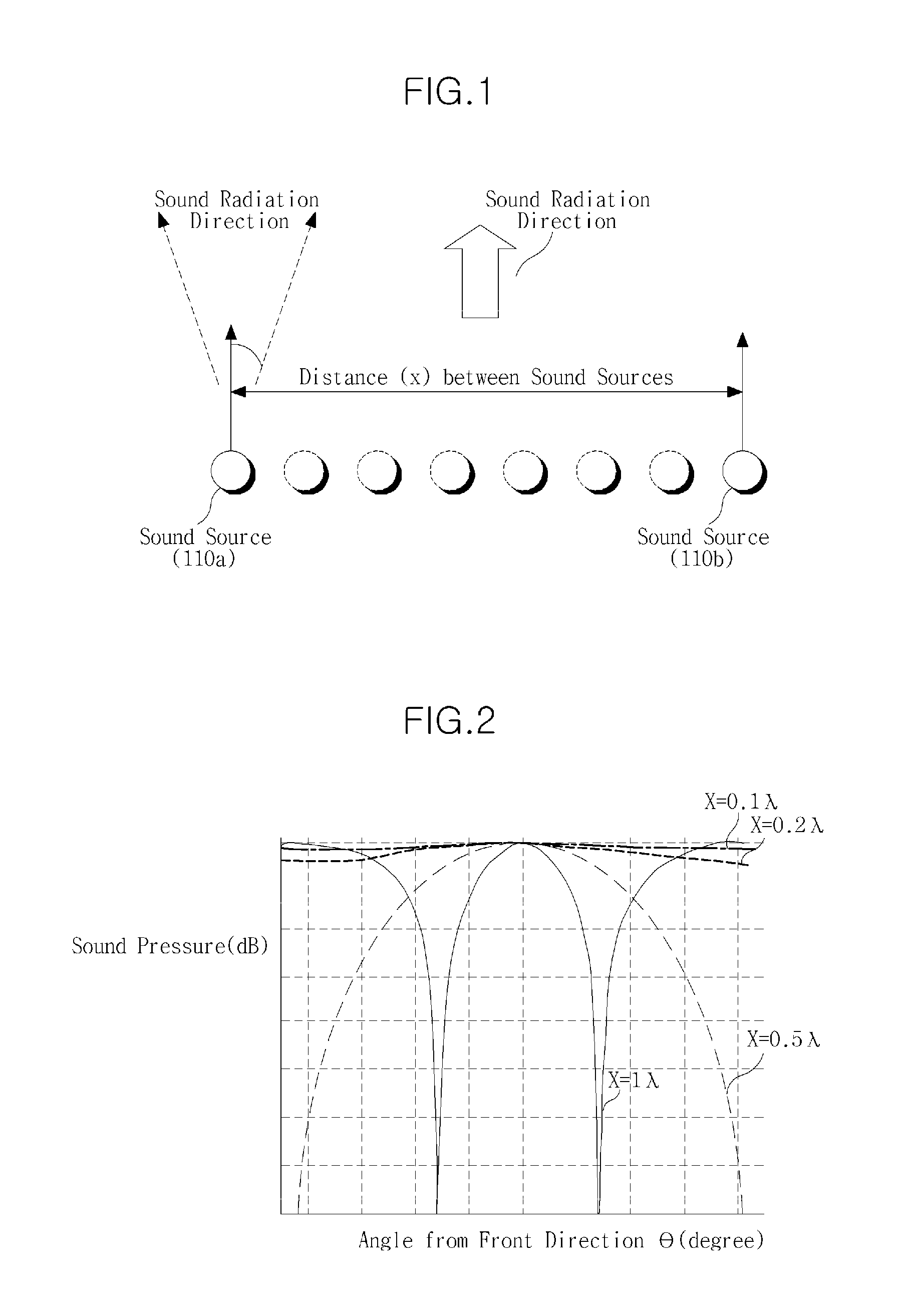
[0036]FIG. 1 illustrates sound radiation patterns of an exemplary sound source clustering.

[0037]Referring to FIG. 1, in a sound source array in which sound sources are arranged in a row, a pair of sound sources 110a and 110b spaced by the same distance from a center of the array may be defined as a sound source cluster. When a distance between the two sound sources 110a and 110b is x, directivity of sound radiation synthesized by the sound source clustering may be expressed as shown in Equation 1:

B(θ)=cos(π(x / λ)sin θ)   [E...


PUM


Abstract

An apparatus and method for generating directional sound are provided to output sound towards a specific sound zone. The apparatus includes an internal loudspeaker array having at least one sound source and edge loudspeakers, each with a sound source having directivity, located at respective ends of the internal loudspeaker array.

Description

CROSS-REFERENCE TO RELATED APPLICATION(S)[0001]This application claims the benefit under 35 U.S.C. §119(a) of a Korean Patent Application No. 10-2008-0125309, filed Dec. 10, 2008, the disclosure of which is incorporated herein in its entirety by reference.BACKGROUND[0002]1. Field[0003]The following description relates to sound processing technology, and more particularly, to an apparatus and method for generating directional sound to be output to a specific sound zone.[0004]2. Description of the Related Art[0005]A sound generating apparatus such as typical loudspeakers cannot output directional sound, and output sound is spread out in all directions. That is, although a sound pressure level may vary depending on a position of a listener, sound is spread out around the sound generating apparatus.[0006]Accordingly, the output sound may act as a disruption when delivered to a person who does not wish to hear it. Although the use of headphones or earphones may enable the output sound to...

Claims


Application Information

Patent Timeline
Patent Type & Authority Applications(United States)
IPC IPC(8): H04R5/02
CPCH04R1/345H04R1/403H04R3/12H04R2430/25H04R2201/405H04R2203/12H04R2201/403H04R1/40H04R1/20H04R1/32
Inventor CHOI, JUNG-WOOKIM, YOUNG-TAEKIM, JUNG-HOKO, SANG-CHUL
Owner SAMSUNG ELECTRONICS CO LTD
Why Eureka
Try Eureka