
Shaft antiseizing type sprocket

a sprocket and shaft technology, applied in the field of shaft antiseizing type sprockets, can solve the problem that the sprocket shaft cannot be removed, and achieve the effect of simple structure and easy installation and replacemen

Inactive Publication Date: 2010-06-10
TANAKA KOJI
View PDF6 Cites 6 Cited by
  • Summary
  • Abstract
  • Description
  • Claims
  • Application Information

AI Technical Summary

Benefits of technology

[0014]According to the present invention, when a shaft bore inner circumferential surface of a boss portion integrally molded with a sprocket teeth portion is installed and fixed to a sprocket shaft, a special fixing tool on a rotating body is not needed and the following effects can be obtained by the claimed sprocket structure.
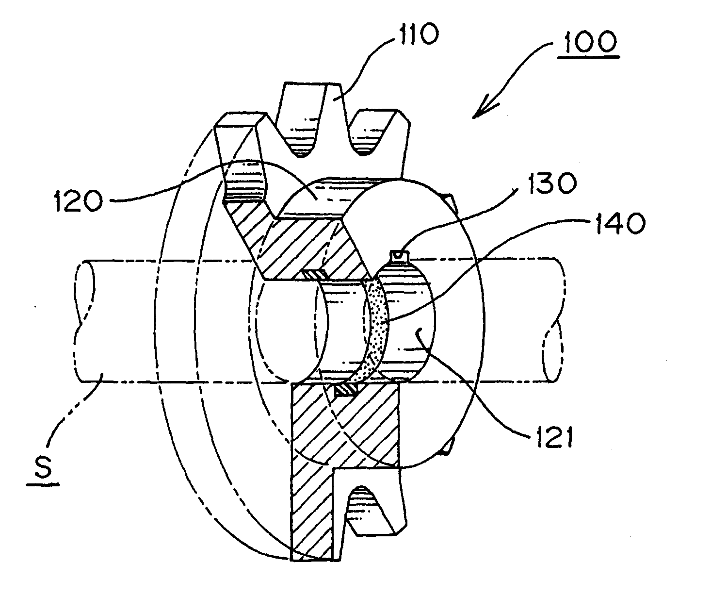
[0015]Namely, a solid lubricant embedded in the boss portion is disposed in a partially exposed state toward the inner circumferential surface of the shaft bore in the boss portion, a solid lubricant, which is gradually softened by heat generated such as by kinetic energy or the like occurring in the sprocket. The lubricant forms an oil film in the gap between the inner circumferential surface of the sprocket shaft bore and the sprocket shaft by swelling and capillary attraction. Thus, seizing liable to occur in the contact portion between the sprocket and the sprocket shaft is avoided by this simple sprocket structure so that an easy installation and replacement can be attained.
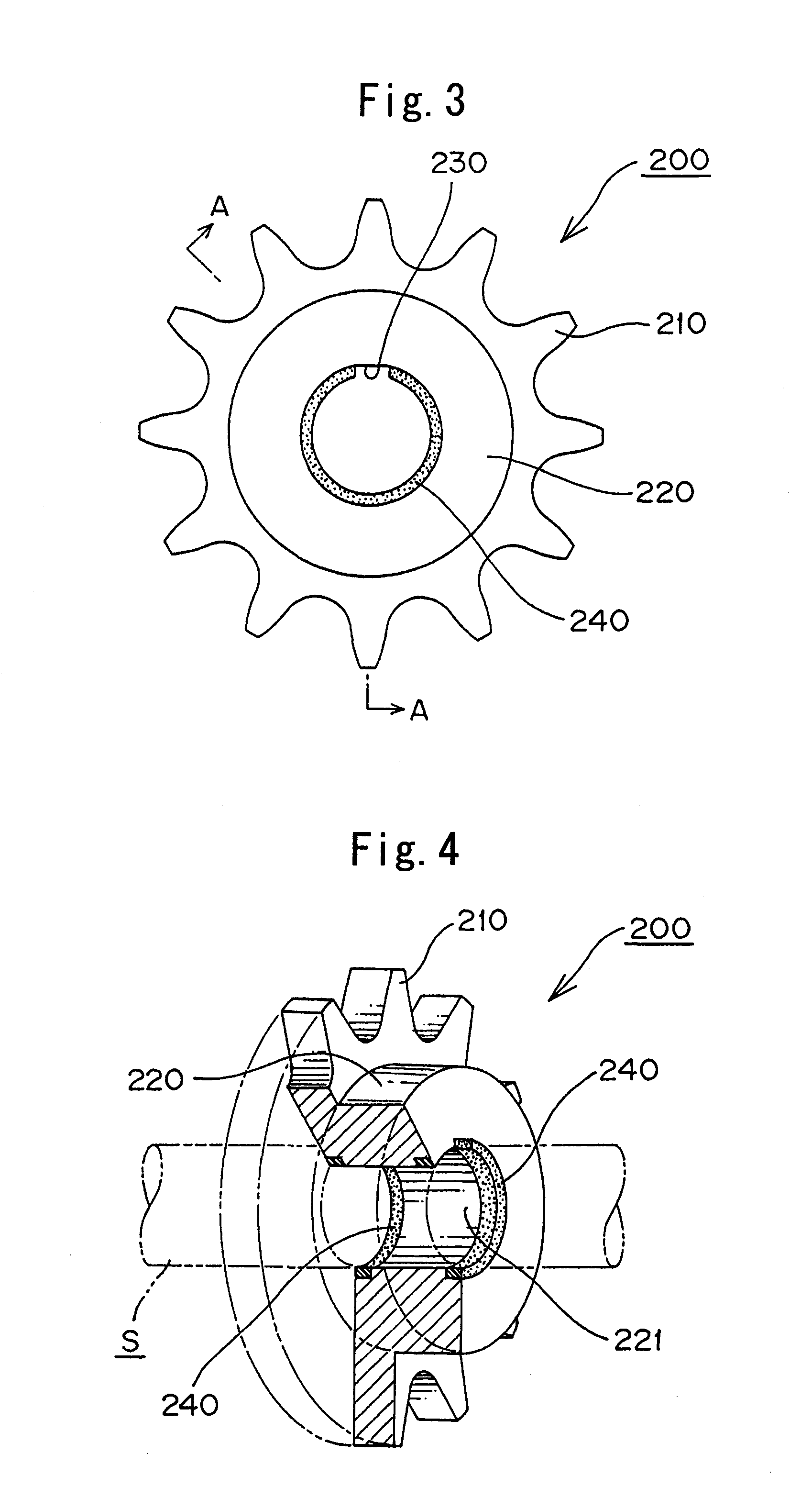
[0016]According to the shaft antiseizing type sprocket of the invention, since the solid lubricant is solidified in polyethylene with lubricant dispersedly held, in addition to the above-mentioned effects obtained by the invention, polyethylene and the solid lubricant is gradually softened by heat generation such as kinetic energy, which occurs in the sprocket during power transmission, and the lubricating oil dispersed and held in polyethylene is gradually diffused. Therefore, lubricating oil enough to form an oil film within a gap between the inner circumferential surface of the sprocket shaft bore and the sprocket shaft can be continuously supplied for a long period of time.
[0017]If in a shaft antiseizing type sprocket in which the inner circumferential surface of the shaft bore in a boss portion integrally molded with a sprocket teeth portion is installed and fixed to a sprocket shaft, a solid lubricant confined in said boss portion is disposed in a partially exposed state toward the shaft bore inner circumferential surface of said boss portion, seizing liable to occur in the contact portion between a sprocket and the sprocket shaft is completely avoided by a simple structure for a long period of time and installation of a replacement sprocket is possible without use of special-purpose tool or mounting tool having a rotating body. Any concrete embodiment of the present invention may be used.

Problems solved by technology

Since heavy seizing is generated at a contact portion with the sprocket shaft with the sprocket depending on a use load and use time of the sprocket to be replaced, the sprocket is impossible to remove from the sprocket shaft.

Method used


Image

  • Shaft antiseizing type sprocket
  • Shaft antiseizing type sprocket
  • Shaft antiseizing type sprocket

Examples


Embodiment Construction

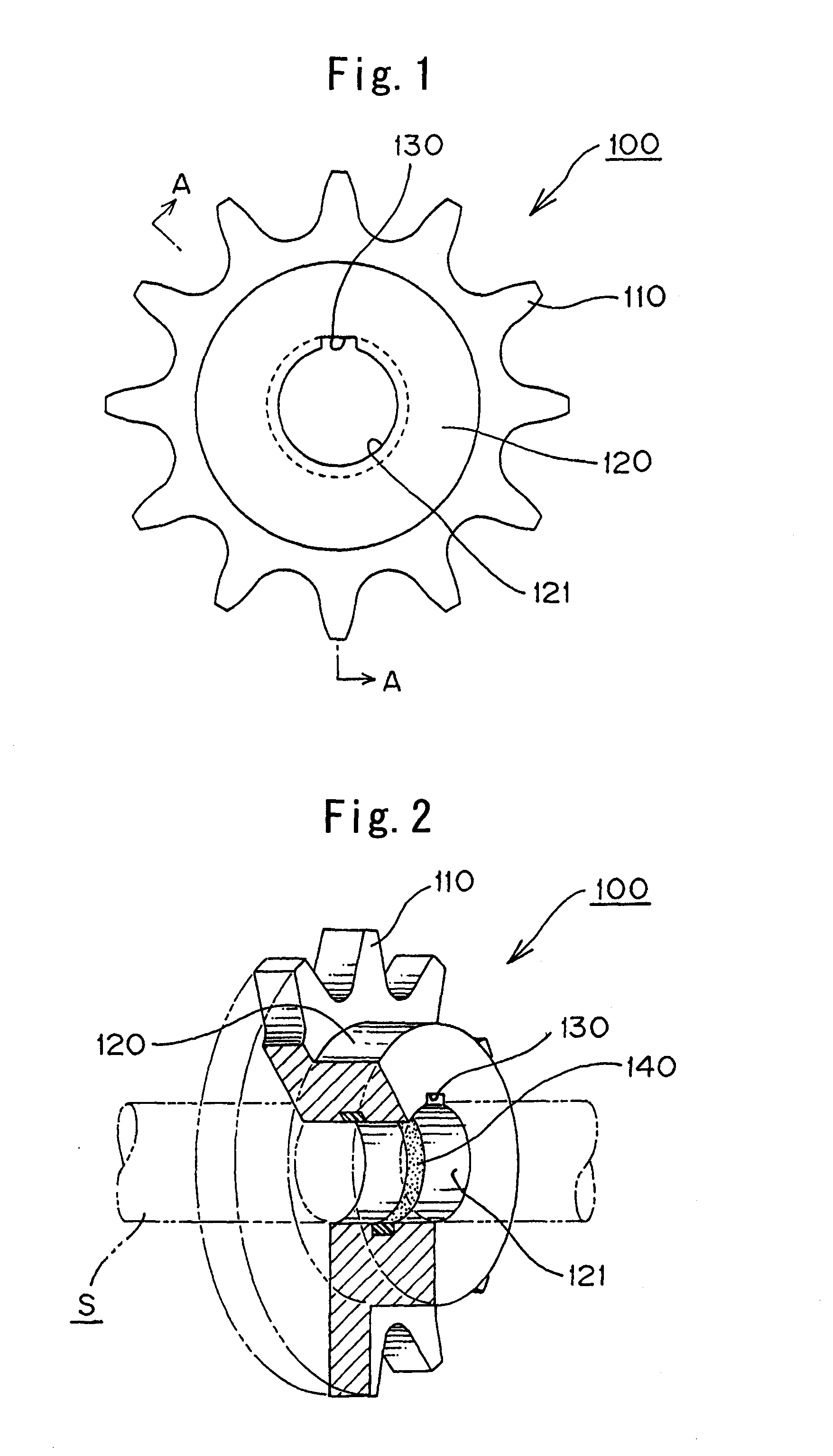
[0032]With reference to FIGS. 1 and 2, a shaft antiseizing type sprocket 100, which is a first example of the present invention, includes sprocket tooth portions 110 and a boss portion 120 integrally molded to the sprocket tooth portions 110, and is formed so that a keyway 130 is formed in an inner circumferential surface 121 of a shaft bore of the boss portion 120. The sprocket 100 is incorporated and fixed to a sprocket shaft S (FIG. 9) in a power transmitting mechanism or the like through a key K which engages a keyway 130. The sprocket 100 can be replaced when wear loss is generated in a sprocket tooth portion 110, or when the number of sprocket teeth is changed or the like.

[0033]A solid lubricant 140 in the form of an annular ring is embodied in the boss portion 120 for avoiding seizing which is liable to occur in the contact portion between the inner circumferential surface 121 of the shaft bore of the sprocket 100 and the sprocket shaft S. The solid lubricant 140 is disposed ...


PUM

PropertyMeasurementUnit
timeaaaaaaaaaa
shapeaaaaaaaaaa
swellingaaaaaaaaaa

Abstract

A shaft antiseizing type sprocket in which seizing liable to occur in the contact portion between the sprocket and the sprocket shaft is completely avoided for a long period of use. Effecting replacement is possible without use of a special-purpose removing tool or a fixing tool with a rotating body. The shaft antiseizing type sprocket has a boss portion which is integrally molded with a sprocket tooth portion. The boss has a shaft bore, the inner circumferential surface of which is adapted to be fixed to a sprocket shaft. A solid lubricant is embedded in the boss portion, and is disposed in a partially exposed state toward the shaft bore inner circumferential surface of the boss portion.

Description

CROSS REFERENCE TO RELATED APPLICATION[0001]This application is a divisional of U.S. application Ser. No. 11 / 947,128 filed Nov. 29, 2007 which claims priority to Japanese Application No. 2007-022433 filed Jan. 13, 2007, the foregoing applications being incorporated herein by reference.FIELD OF INVENTION[0002]The present invention relates to a sprocket, which is incorporated and fixed to a sprocket shaft in a power transmission mechanism, and more specifically it relates to a shaft antiseizing type sprocket, in which seizing with a sprocket shaft is prevented and installation replacement is possible.BACKGROUND OF THE INVENTION[0003]When damage such as wear or the like is generated in a sprocket tooth portion, a sprocket, which is installed and fixed to a sprocket shaft in a power transmission mechanism or the like, is replaced. Since heavy seizing is generated at a contact portion with the sprocket shaft with the sprocket depending on a use load and use time of the sprocket to be rep...

Claims


Application Information

Patent Timeline
Patent Type & Authority Applications(United States)
IPC IPC(8): F16H55/30F16B3/00C10M107/04C10M169/00C10N30/00C10N30/06C10N40/00C10N50/08
CPCF16D1/0876F16H55/30Y10T403/7021Y10T74/19991F16H57/041
Inventor TANAKA, KOJI
Owner TANAKA KOJI
Learn More