Metalannular Gasket

a gasket and metal technology, applied in the direction of threaded fasteners, sealing, washing machines, etc., can solve the problems of damaging the neck portion and screw portion of the tightening means, and achieve the effects of improving durability, preventing the dropout of the gasket, and improving the applicability of attaching

Active Publication Date: 2010-06-10
UCHIYAMA MFG
View PDF30 Cites 21 Cited by
  • Summary
  • Abstract
  • Description
  • Claims
  • Application Information

AI Technical Summary

Benefits of technology

[0012]The metal annular gasket of the present invention has rigidity by the annular metal base plate. Further, the compound layer integrally laminated on the both surfaces of the annular metal base plate is formed by mixing a fiber material in synthetic resin or a rubber material, so the synthetic resin or the rubber material is carried by the fiber material to give toughness. In addition, when two members are fastened by inserting the tightening means such as bolts in the inner hole, the synthetic resin or the rubber material does not drift by the carried force, thereby keeping the gasket function. The circumferential covering portion constituting the annular seal layer made of synthetic resin or a rubber material is designed to cover the inner circumferential edge of the annular metal plate and the inner circumferential edge of the both compound layers, so that the tightening means can be elastically engaged into the circumferential covering portion when the tightening means is inserted in the inner hole, thereby preventing dropout of the gasket during conveyance and transportation and its damage. Further, the surface in the thickness direction of the annular seal layer is formed same as the surface of the compound layer, and the tightening load is applied on the annular seal layer and the compound layer, so that fatigue of the annular seal layer because of the concentrated load is not caused and the durability is improved. The compressed annular seal layer and compound layer are interposed in the fastened portion to give sound and vibration insulation property, thereby improving applicability for attaching and fixing the cover member such as the rocker cover and the oil pan of the engine and for fitting sensors such as a pressure sensor and a temperature sensor.
[0013]When the portion around the inner circumference of each compound layers is compressed into the thickness direction with a constant width to form the compressed flat layer portion and the covering layer portion as one part of the annular seal layer is integrally attached on the surface of the compressed flat layer portion, the covering layer portion is compressed together with the compound layer in case of fastening because the covering layer portion is made of synthetic resin or a rubber material, thereby obtaining a superior sealing ability of the fastened portion by the contact pressure. Further, the surface of the covering layer portion is designed to be same as the surface of the compound layer except for the compressed flat layer portion, so that the fastening load is applied on the covering layer portion and the compressed flat layer portion as a part of the compound layer, thereby preventing fatigue of the annular seal layer including the covering layer portion caused by the concentrated load and improving the durability.
[0014]At the boundary portion of the circumferential covering portion and the inner circumferential edge of the both compound layers, when a part of the synthetic resin or the rubber material constituting the annular seal layer penetrates between the fiber material constituting the compound layer to be integrally fixed each other, in addition to the above-mentioned effects, the circumferential covering portion can be easily formed and it, namely the annular seal layer and the compound layer, is strongly integrated.
[0015]When a ring-like salient projecting into the centrifugal direction is formed along the circumferential direction in the inner circumferential face of the circumferential covering portion, prevention effect of dropout and damage on the fastening means can become remarkable by the elastic holding action of the ring-like salient.
[0016]Further, a chevron shaped annular bead portion is concentrically formed on the surface in the thickness direction side of the annular seal layer, the bead portion is compressed during fastening and superior sealing ability can be obtained by the strong contact pressure by the reaction force.

Problems solved by technology

However, such a dropout prevention process requires an extra process during production of a washer seal, and sometimes damages the neck portion and screw portion of the tightening means.

Method used


Image

  • Metalannular Gasket
  • Metalannular Gasket
  • Metalannular Gasket

Examples


Embodiment Construction

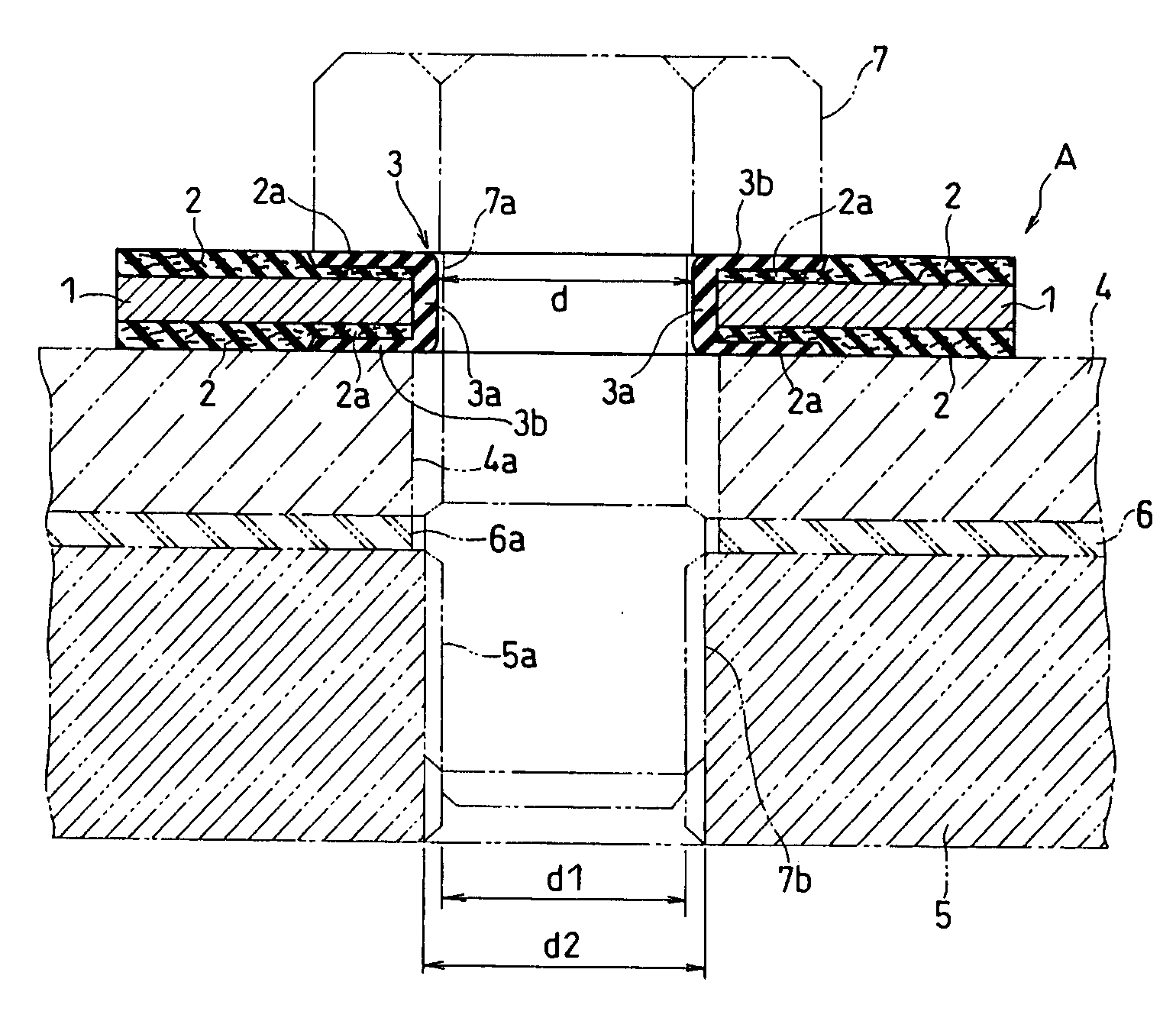
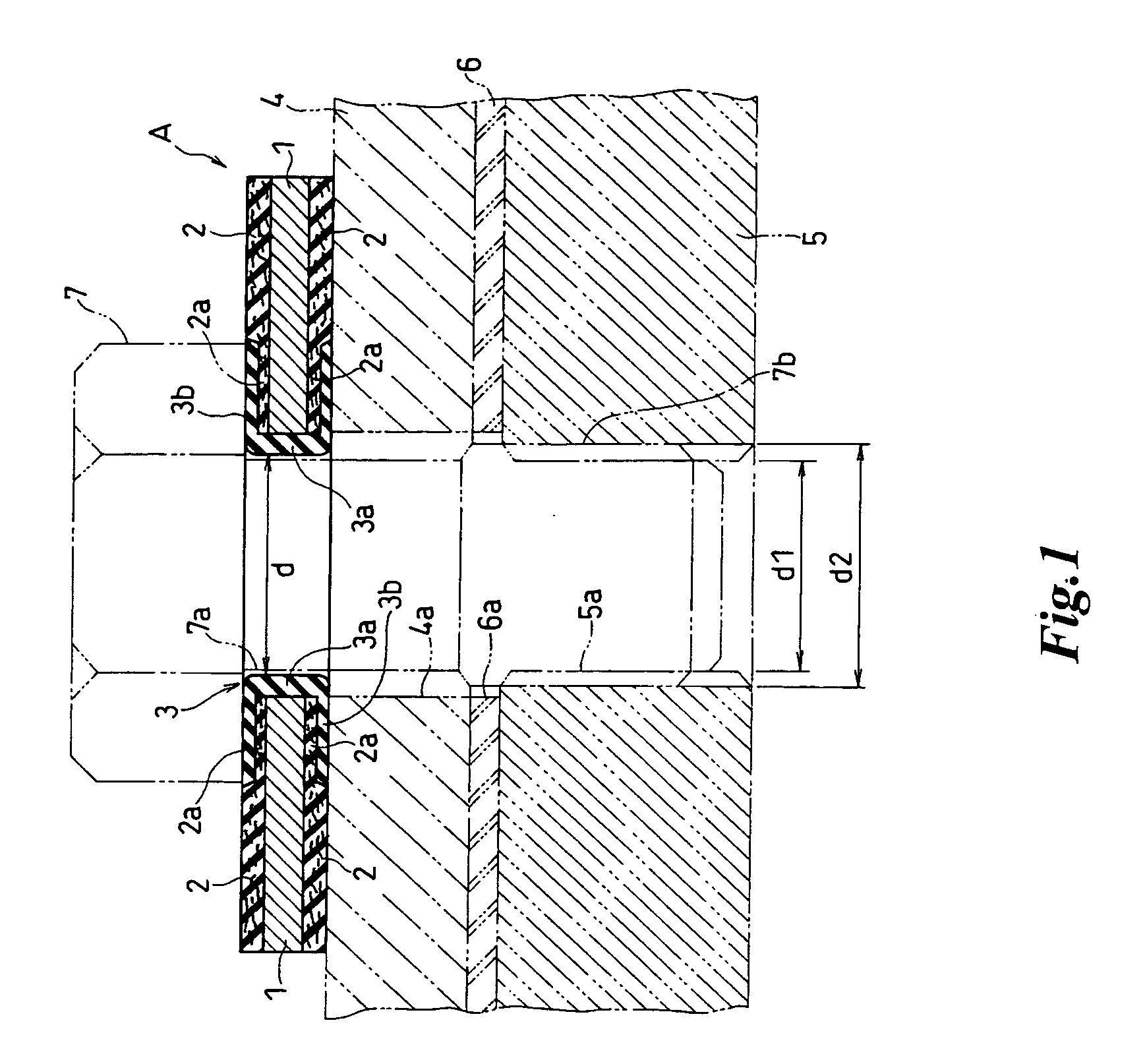
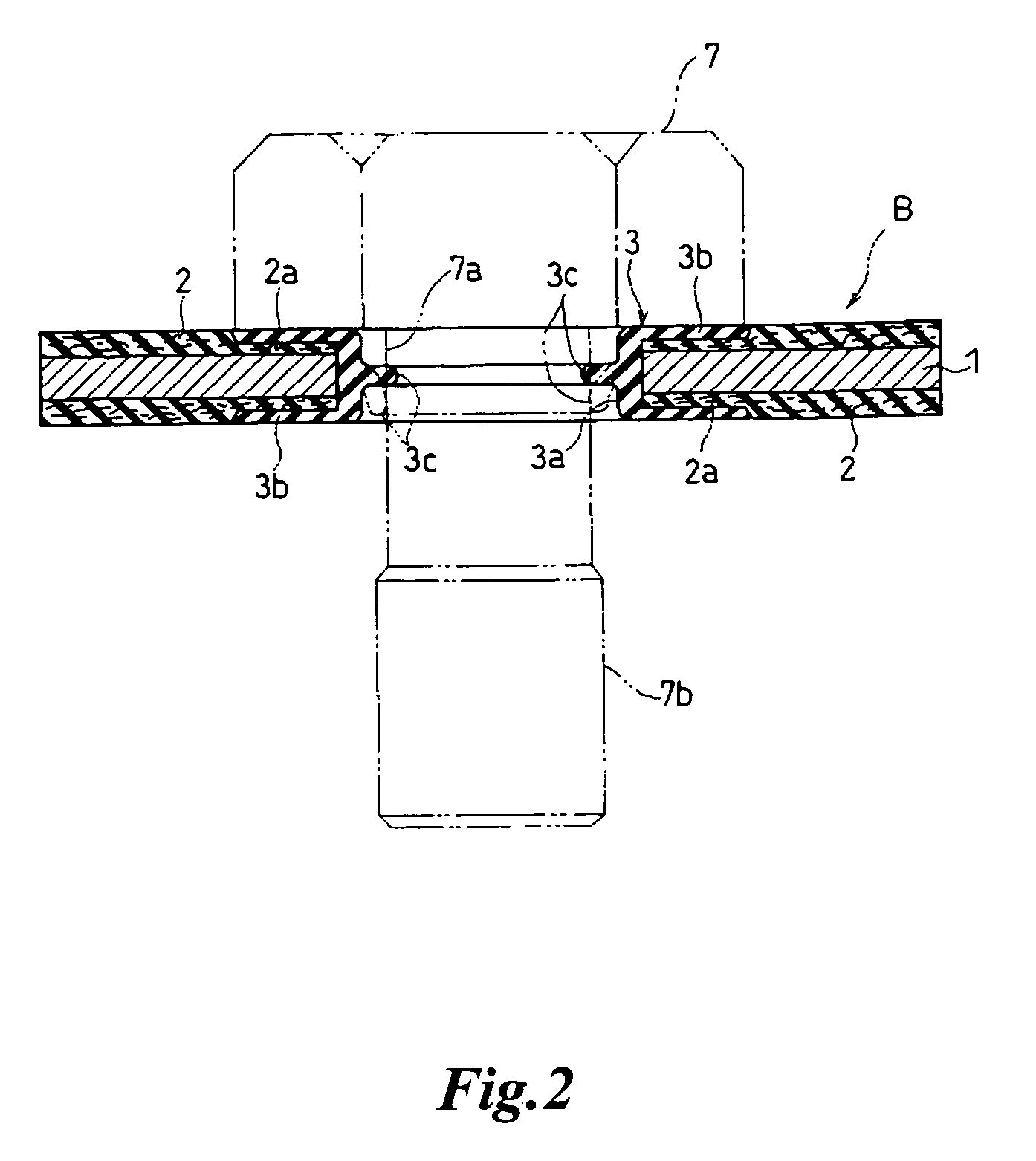
[0032]The best mode for carrying out the present invention is explained hereinafter based on the drawings. FIG. 1 is a sectional view showing an embodiment of the metal annular gasket of the present invention. FIGS. 2-5 show a sectional view of other embodiment, respectively. FIG. 6 is an explanatory view showing how the metal annular gasket of the embodiment in FIG. 5 is manufactured.

[0033]According to the metal annular gasket A in FIG. 1, a compound layer 2, 2 is formed on both surfaces of an annular metal base plate 1 made of steel sheet like an aluminum plate and a stainless steel sheet. The compound layer 2 is formed by laminating a compound material in which an organic or inorganic fiber material and additive (rubber agent, filler and the like) are mixed with synthetic resin or a rubber material. The compound material in the figure is formed by mixing a fiber material with a rubber material, thus formed compound material is imprinted on the metal plate with a roll via adhesive...


PUM

PropertyMeasurementUnit
thicknessaaaaaaaaaa
elasticityaaaaaaaaaa
durabilityaaaaaaaaaa

Abstract

A metal annular gasket comprising an annular metal base plate; a compound layer integrally laminated on both surfaces of the annular metal base plate, the compound layer being made of synthetic resin or a rubber material mixed with a fiber material; and an annular seal layer having a circumferential covering portion which covers the inner circumferential edge of the annular metal plate and the inner circumferential edge of both compound layers, the compound layer being made of synthetic resin or a rubber material. The annular seal layer is formed such that the surface of the annular seal layer is so connected to the surfaces of the compound layer as to provide smooth transition in its thickness direction.

Description

TECHNICAL FIELD[0001]The present invention relates to a metal annular gasket designed to be attached to the neck portion of a bolt and a stud bolt for fitting covers, a male screw for fitting sensors such as a pressure sensor or a temperature sensor.BACKGROUND ART[0002]Conventionally, bolts are arranged at appropriate portions of a covering member and a tightening means is executed while interposing a gasket attached around the covering member between the mounting portion and the bolt, thereby enabling to attach and fix the covering member such as the rocker cover and the oil pan of the engine to the mounting portion. Washer seal (metal annular gasket) having elasticity is interposed between the tightening means and the covering member in order to achieve sealing around the tightening means and sound and vibration control of the covering member. When the sensors like a pressure sensor and a temperature sensor are fitted on a mounting portion, a similar washer seal is interposed betw...

Claims


Application Information

Patent Timeline
Patent Type & Authority Applications(United States)
IPC IPC(8): F16B43/00F16J15/12
CPCF16B41/002F16J15/104Y10S277/937F16B43/001
Inventor MATSUMOTO, KENJITAKAHASHI, KAZUHIRO
Owner UCHIYAMA MFG
Why Eureka
Try Eureka