Ultrasound diagnosis apparatus

Active Publication Date: 2010-06-10
FUJIFILM HEALTHCARE CORP
View PDF9 Cites 2 Cited by
  • Summary
  • Abstract
  • Description
  • Claims
  • Application Information

AI Technical Summary

Benefits of technology

[0010]In order to achieve at least the advantage described above, according to one aspect of the present invention, there is provided an ultrasound diagnosis apparatus comprising an array transducer having a plurality of transducer elements, a transmitting unit which outputs a transmission signal to the plurality of transducer elements, and a receiving unit which applies a reception weight on a reception signal obtained from the plurality of transducer elements in a receive aperture, based on a position of each transducer element in the receive aperture, wherein the receiving unit shifts a position of a peak of the reception weights in the receive aperture, to follow a movement of the reception beam.
[0011]With the structure of the above-described aspect of the present invention, because the position of the peak of the reception weights is shifted in the receive aperture to follow

Problems solved by technology

When the distribution of the weights is set symmetrical and the position of the peak of the reception weights and the position of the center of the receive aperture are matched regardless of the position of the ultrasound beam, if the position of the peak of the rece

Method used


Image

  • Ultrasound diagnosis apparatus
  • Ultrasound diagnosis apparatus
  • Ultrasound diagnosis apparatus

Examples


Embodiment Construction

[0018]A preferred embodiment of the present invention will now be described.

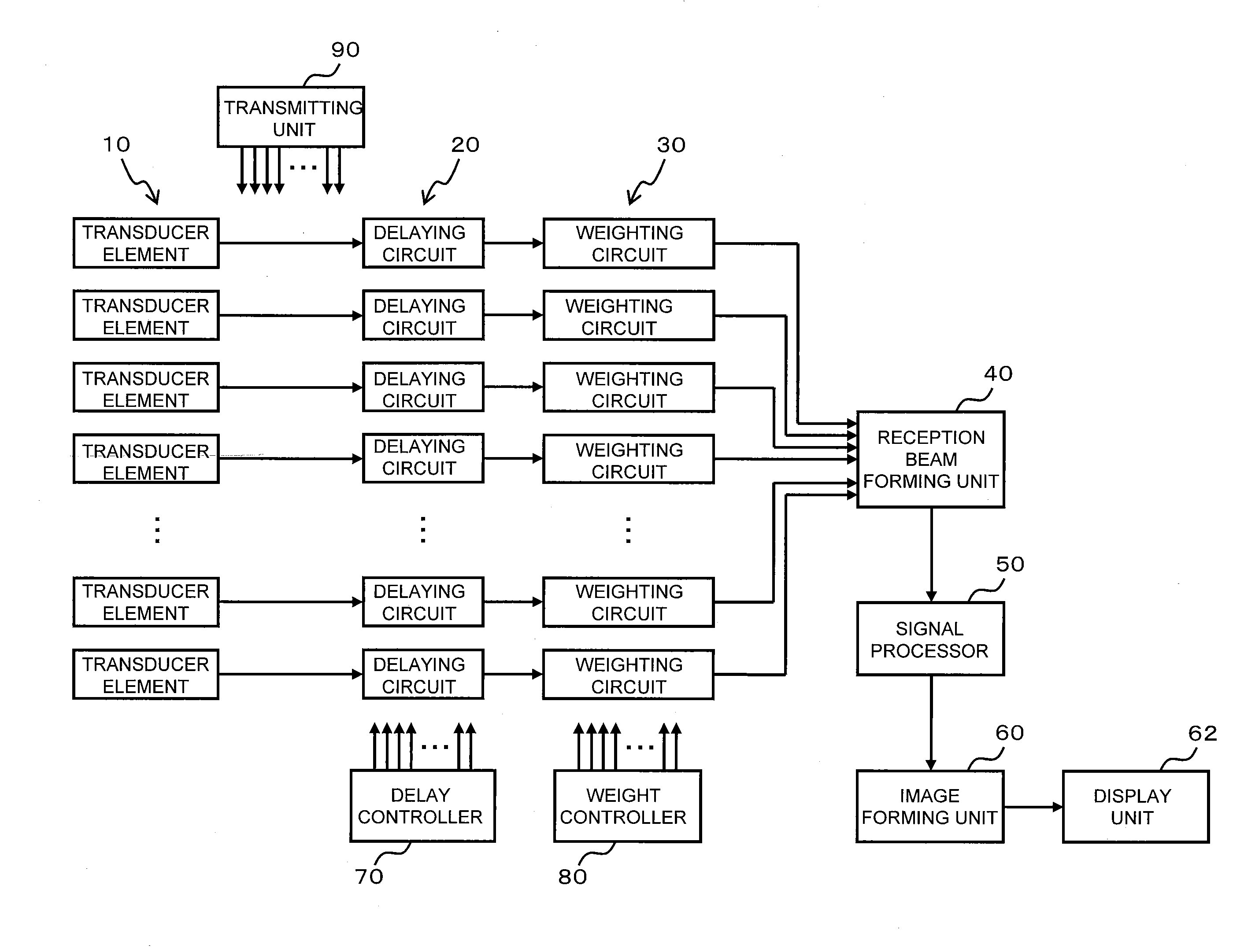
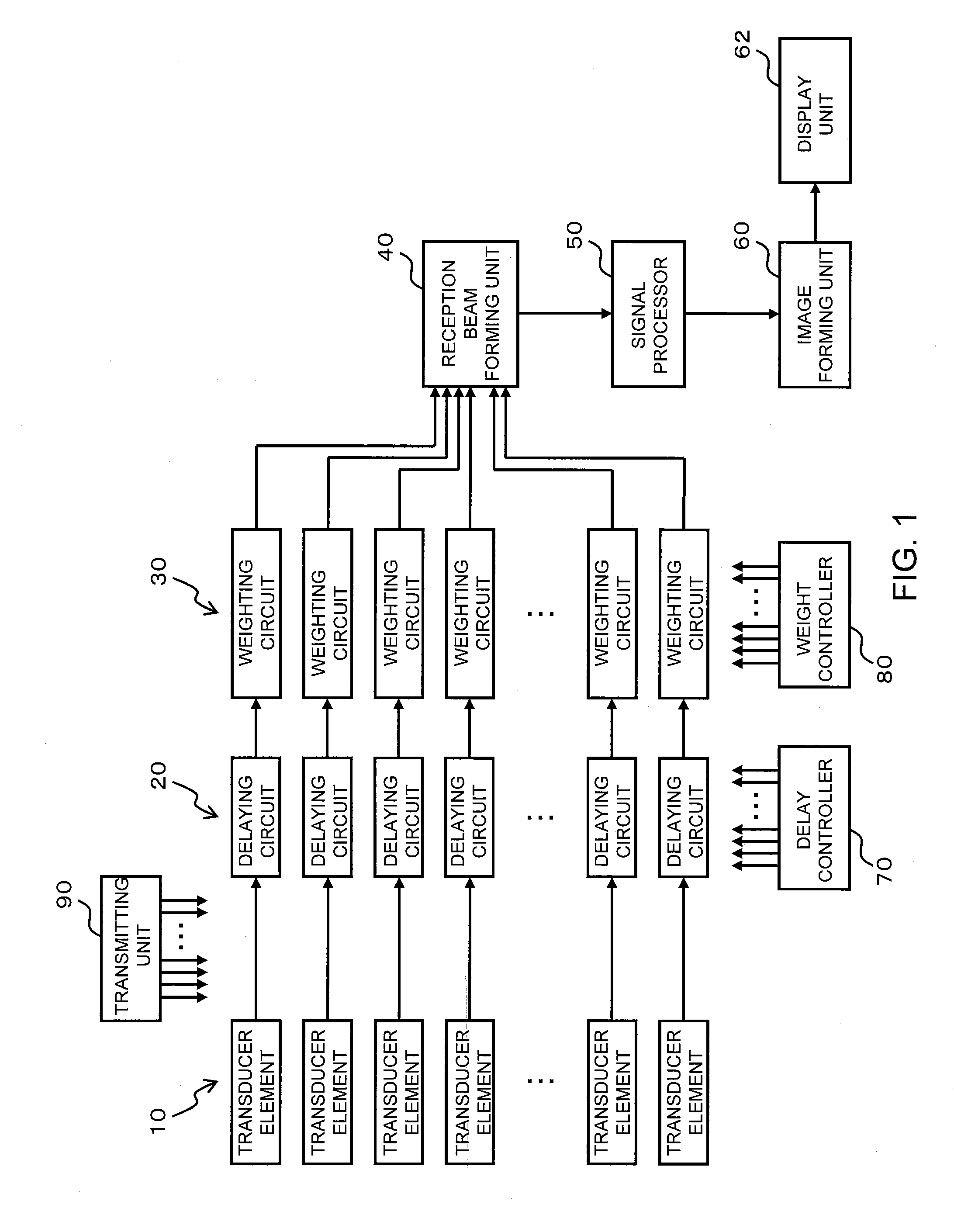
[0019]FIG. 1 shows an ultrasound diagnosis apparatus according to a preferred embodiment of the present invention, and is a functional block diagram showing an overall structure of the ultrasound diagnosis apparatus.

[0020]An ultrasound diagnosis apparatus shown in FIG. 1 comprises an array transducer having a plurality of transducer elements 10. The plurality of transducer elements 10 are arranged in a one-dimensional manner. In the present embodiment, for example, a linear-type probe or a convex-type probe is formed by the plurality of the transducer elements 10.

[0021]The plurality of transducer elements 10 vibrate according to a transmission signal which is output from a transmitting unit 90, and transmit an ultrasound to, for example, a living body. The transmitting unit 90 supplies a transmission signal to each of the plurality of transducer elements 10. In this process, a delay process or the like is ap...


PUM


Abstract

In FIG. 2 (A), a reception beam (102) is formed using a weighting function (112). A position of a peak of the weighting function (112) is set at the position of the reception beam (102). A reception beam (104) is formed using a weighting function (114), and a position of a peak of the weighting function (114) is set at the position of the reception beam (104). A reception beam (106) is formed using a weighting function (116) and a position of a peak of the weighting function (116) is set at a position of the reception beam (106). In this manner, the positions of the peaks of the weighting functions (112, 114, 116) are shifted in the receive aperture, to follow movements of the reception beams (102, 104, 106) caused by electrical scanning.

Description

BACKGROUND[0001]1. Technical Field[0002]The present invention relates to an ultrasound diagnosis apparatus, and in particular to processing of a received signal.[0003]2. Related Art[0004]An array-type ultrasound transducer (array transducer) having an array of transducer elements comprising a plurality of transducer elements is known. In addition, in order to reduce side lobes of ultrasound beam during transmission and reception of the ultrasound using the array transducer, a technique is known in which weights are assigned according to positions of the transducer elements in a transmit aperture or a receive aperture.[0005]For example, JP Hei 7-116163 A (Patent Document 1) discloses a technique of reception weighting in which the distribution of the weights is set symmetrical. In Patent Document 1, a position of a peak of the reception weights and the position of the center of the receive aperture are matched regardless of the position of the ultrasound beam (refer to FIG. 9 of Pate...

Claims


Application Information

Patent Timeline
IPC IPC(8): A61B8/14
CPCA61B8/00G01S15/8918G01S7/52047A61B8/54
Inventor TSAO, JING-WENHISATSU, MASANORI
Owner FUJIFILM HEALTHCARE CORP
Why Eureka
Try Eureka