System and method for treating septal defects

a septal defect and system technology, applied in the direction of catheters, etc., can solve the problems of difficult introduction and advancement of such devices into vessels, damage or rendered inoperable, and the loading of such devices

Inactive Publication Date: 2010-06-10
MINNESOTA MEDTEC INC
View PDF50 Cites 8 Cited by
  • Summary
  • Abstract
  • Description
  • Claims
  • Application Information

AI Technical Summary

Benefits of technology

[0009]In another embodiment, the elongated tubular member of the previous embodiment may also include a second connection element near a proximal end. In another embodiment, the second connection element may be a luer connector. In another embodiment, an inner diameter of the elongated tubular member may be substantially the same as an inner diameter of the catheter, the inner diameters and the abutting relationship providing for a smooth transition between the elongated tubular member and the catheter. In another embodiment, the elongated tubular member is substantially hollow and unobstructed. In another embodiment, the elongated tubular member is adapted to receive an expanding nitinol mesh and allow the mesh to pass smoothly there through. In another embodiment, the system may be adapted to provide continuous uninterrupted external support to the mesh as the mesh is first received by the elongated tubular member and further advanced into the catheter. In another embodiment, the elongated tubular member may further include a substantially constant circular inner and outer cross-section and a substantially hollow and unobstructed internal cylindrical volume adapted to receive a first medical device and allow the device to pass there through. In still another embodiment, the first connection element may be sleevably positioned over the elongated tubular member and securely adhered thereto. In yet another embodiment, the elongated tubular member may further include grooves in the outer surface at the location of the first connection element. In another embodiment, the first connection element further comprises a sealing element. In yet another embodiment, the sealing element may be generally tubular with a constant inner diameter and a tapering outer diameter, the outer diameter decreasing from the proximal end to the distal end, the sealing element extending distally from the back wall first connection element and being positioned concentrically with the inner cylindrical volume of the elongated tubular member.

Problems solved by technology

One problem with current guide catheters is that they are damaged or rendered inoperable due to weakness in the materials as a result of the insertion of current expandable nickel titanium devices or devices with sharp components.
Often the introduction and advancement of such a device into a vessel is difficult because the device is either too flexible or has a geometry that doesn't facilitate introduction.
Further, loading such a device may damage the primary tip or, in the case of an intravascular device, the intravascular portion.

Method used


Image

  • System and method for treating septal defects
  • System and method for treating septal defects
  • System and method for treating septal defects

Examples


Embodiment Construction

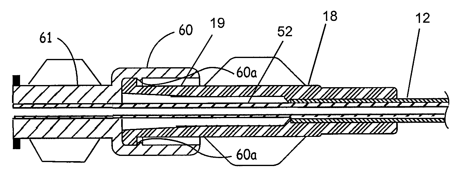
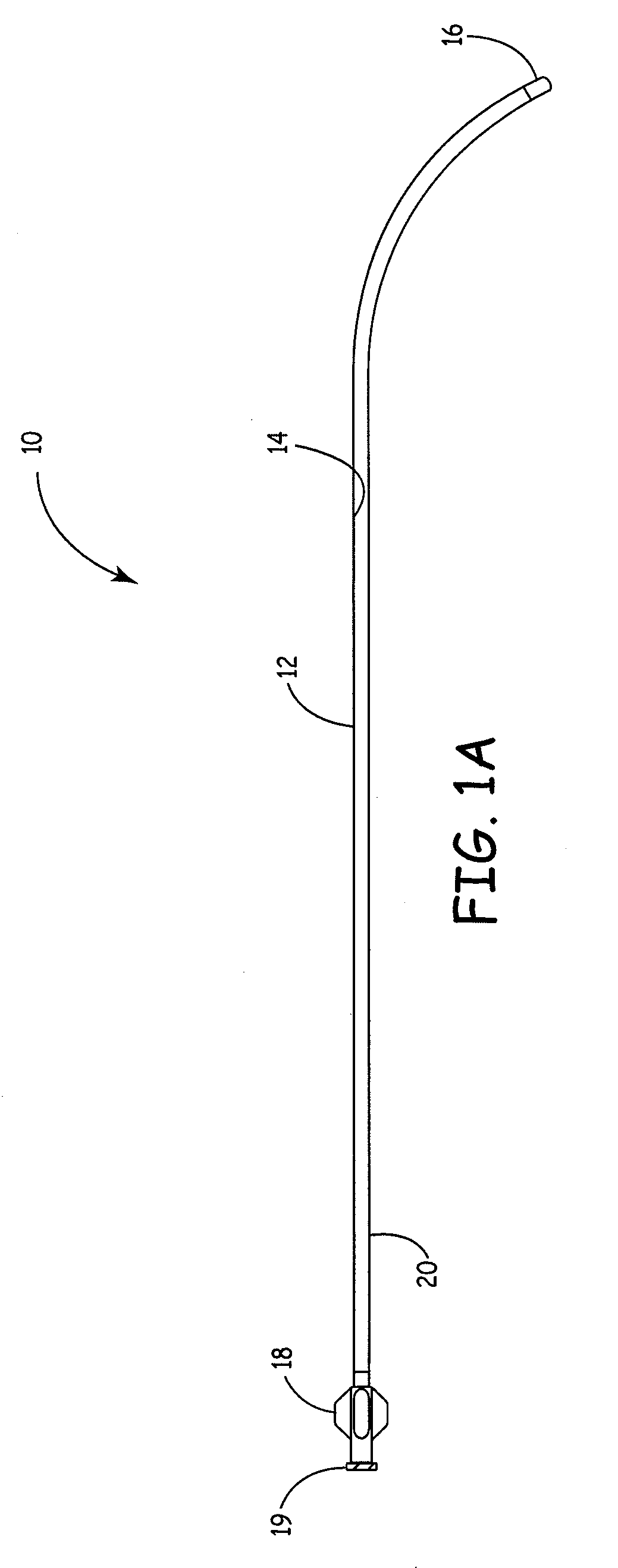
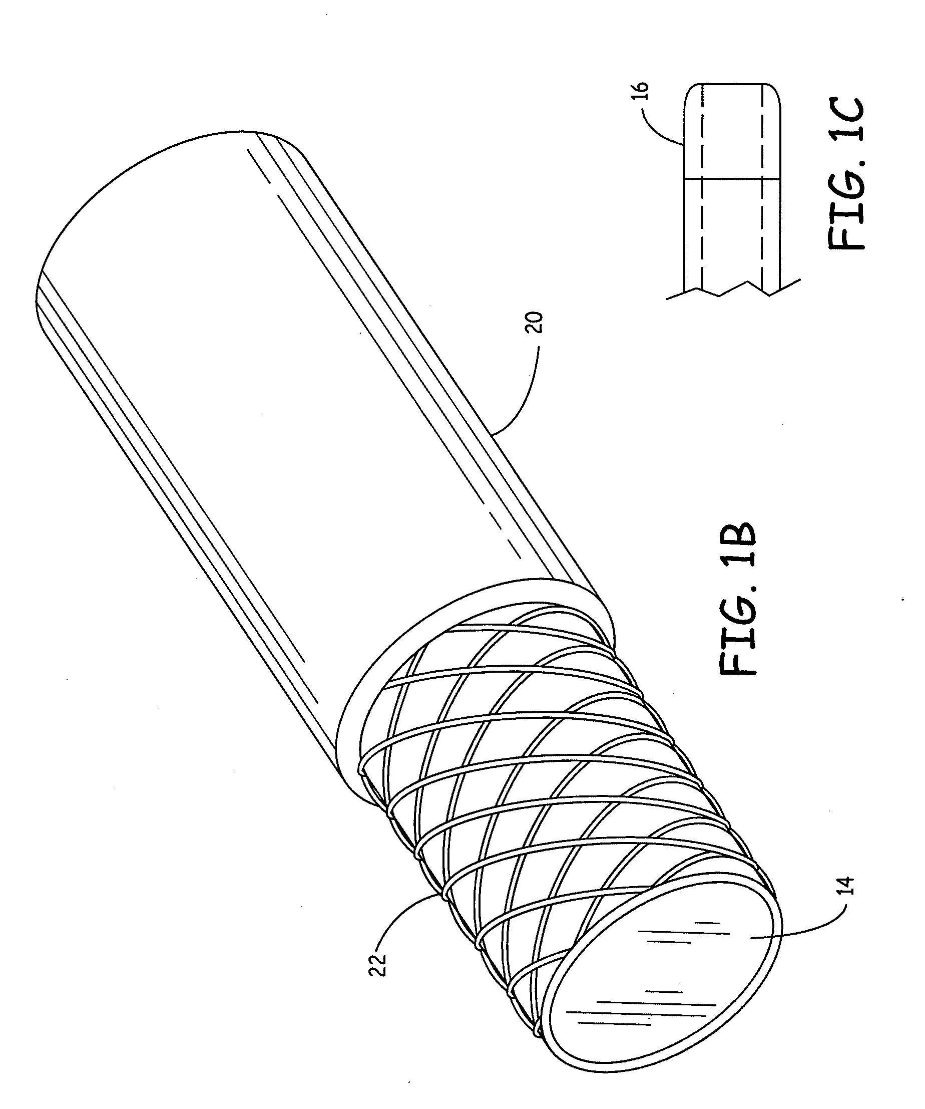
[0037]FIG. 1A depicts a guide catheter 10 according to one embodiment of the present invention. The guide catheter 10 has an elongated tubular member 12 having an inner layer 14, a catheter tip 16, a connection element 18 including a male element 19, and an outer layer 20. According to one embodiment, the guide catheter 10 is a sheath guide catheter configured to be used in conjunction with a dilator guide catheter wherein the dilator is inserted into the sheath, as will be described in further detail herein.

[0038]The inner layer 14 according to one embodiment has a thickness of from about 0.0015 inches to about 0.006 inches. The layer 14 further may be a slippery inner surface configured to promote the advancement of any device inserted into the guide catheter 10. According to one embodiment, the layer 14 is any fluoropolymer. For example, according to one embodiment the layer 14 is comprised of PTFE. Alternatively, the layer 14 is comprised of MFA. In a further alternative, the in...


PUM


Abstract

A system for introducing and advancing medical devices into vessels, including an introducer with a first elongated tubular member having a first connection element at a distal end and a guide catheter comprising a second connection element at a proximal end, the first and second elongated tubular members being substantially hollow for receiving and passing through an expandable device for treatment of septal defects, where the first connection element includes a female connection element with an internal continuous annularly shaped protruding rib; and the second connection element comprises a male connection element adapted to be inserted into the first connection element, the second connection element having an external continuous annularly shaped protruding rib, where the internal rib and external rib are configured to interlock and resist relative longitudinal movement while allowing relative rotational movement. Methods of making and using are also described as well as an associated cutting apparatus.

Description

CROSS-REFERENCE TO RELATED APPLICATION(S)[0001]This application is a continuation-in-part application of, and claims priority to, the following applications: U.S. patent application Ser. No. 12 / 533,908, filed on Jul. 31, 2009, entitled Guide Catheter and Method of Making Same, which application is a continuation application of U.S. patent application Ser. No. 10 / 818,135 filed on Apr. 5, 2004, entitled Guide Catheter and Method of Making Same, which application claims priority to U.S. provisional application No. 60 / 460,544, filed Apr. 4, 2003; and U.S. patent application Ser. No. 10 / 818,089 filed on Apr. 5, 2004, entitled Introduction Apparatus, which application claims priority to U.S. provisional application No. 60 / 460,696, filed Apr. 4, 2003. Each of the above listed applications are hereby incorporated herein by reference in their entireties.FIELD OF THE INVENTION[0002]The present invention relates to a guide catheter and a method of manufacturing the guide catheter. Further, the...

Claims


Application Information

Patent Timeline
Patent Type & Authority Applications(United States)
IPC IPC(8): A61M25/16
CPCA61M25/0012A61M25/0013A61M25/0097A61M25/0069A61M25/005
Inventor PACKARD, BRIAN M.
Owner MINNESOTA MEDTEC INC
Why Eureka
Try Eureka