Machine tool spindle structure capable of monitoring working state in real time

Inactive Publication Date: 2010-06-10
IND TECH RES INST
View PDF8 Cites 56 Cited by
  • Summary
  • Abstract
  • Description
  • Claims
  • Application Information

AI Technical Summary

Benefits of technology

[0008]In the conventional method for measuring a working state of a machine tool spindle, if an inspecting device is disposed out of the machine tool, acquired working parameters cannot really reflect the working state of a cutter; if the inspecting device is disposed in the machine tool spindle, required electric power is generated by an induction coil, but a magnetic field generated by the induction coil directly interferes with measurement or wireless transmission, such that real-time and accurate working parameters of the conventional machine tool spindle cannot be acquired. Accordingly, the present invention is directed to a machine tool spindle structure capable of reducing influence on measurement of real working parameters.
[0009]The present invention provides a machine tool spindle structure capable of monitoring a working state in real time, which includes a spindle body, a rotating mandrel, a cutter base, and an internal inspecting device. The cutter base is detachably combined with the rotating mandrel, the rotating mandrel has a chamber, and the internal inspecting device is disposed in the chamber. The internal inspecting device has a control substrate and an inspecting substrate separated from each other, a battery is disposed on the control substrate and is disposed on the rotating mandrel, and the inspecting substrate is directly disposed on a rotating center on a back side of the cutter base. The inspecting substrate has a plurality of inspecting chips, and the inspecting substrate is electrically connected

Problems solved by technology

In the conventional method for measuring a working state of a machine tool spindle, if an inspecting device is disposed out of the machine tool, acquired working parameters cannot really reflect the working state of a cutter; if the inspecting device is disposed in the machine tool spindl

Method used


Image

  • Machine tool spindle structure capable of monitoring working state in real time
  • Machine tool spindle structure capable of monitoring working state in real time
  • Machine tool spindle structure capable of monitoring working state in real time

Examples


Embodiment Construction

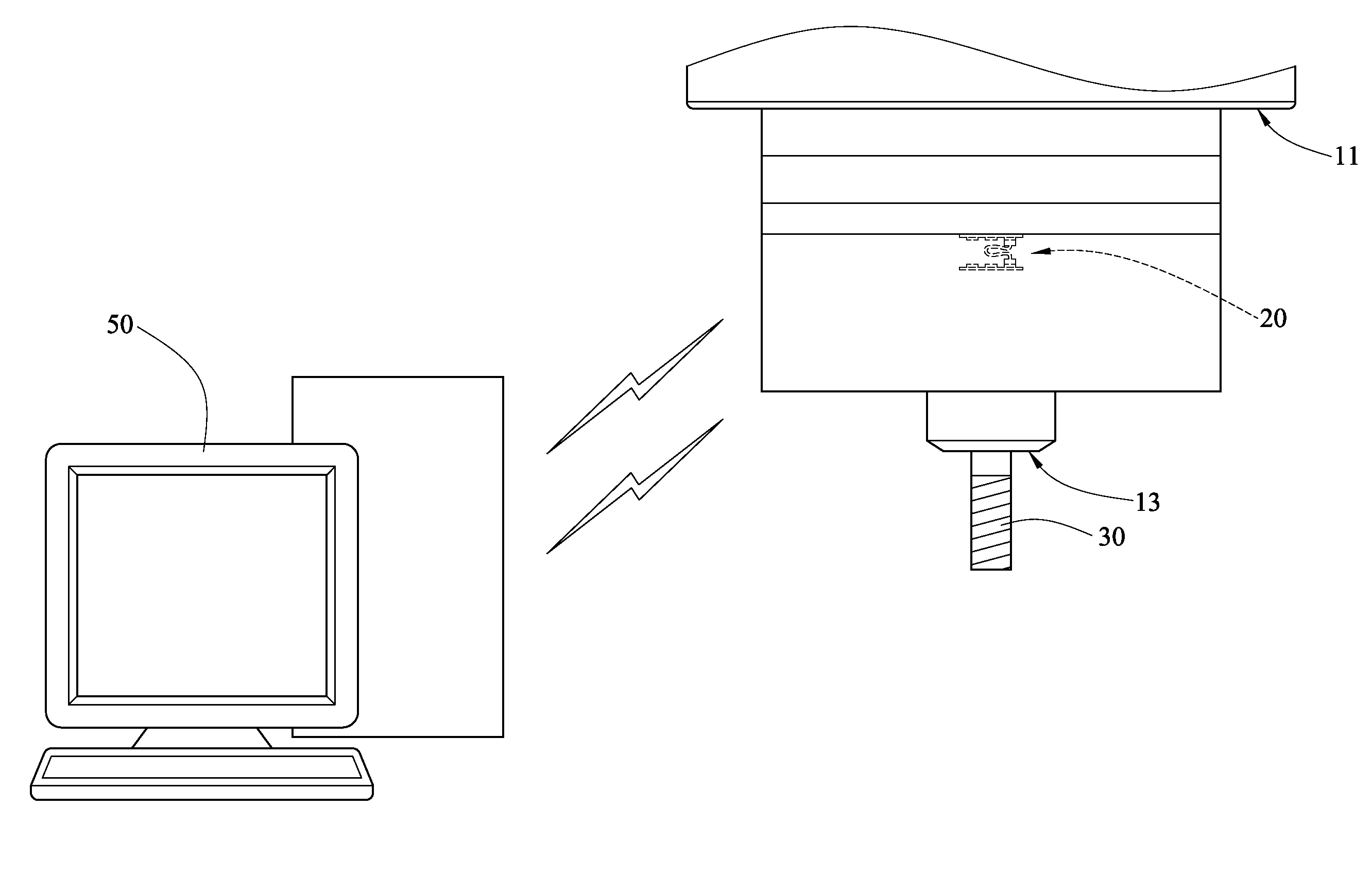
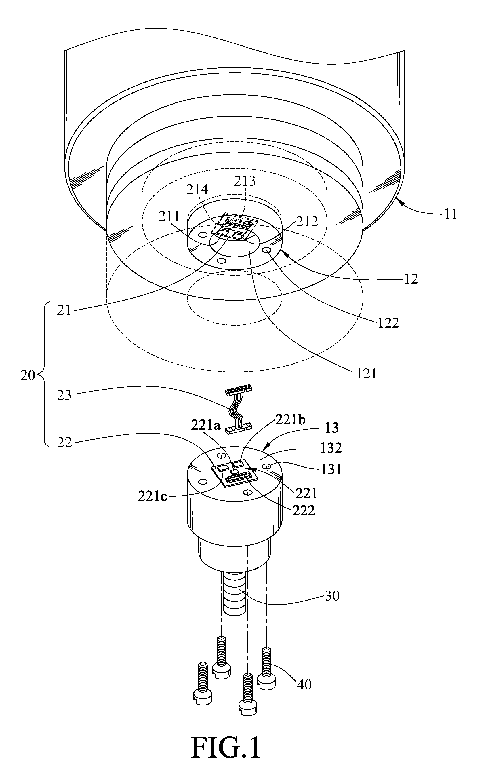
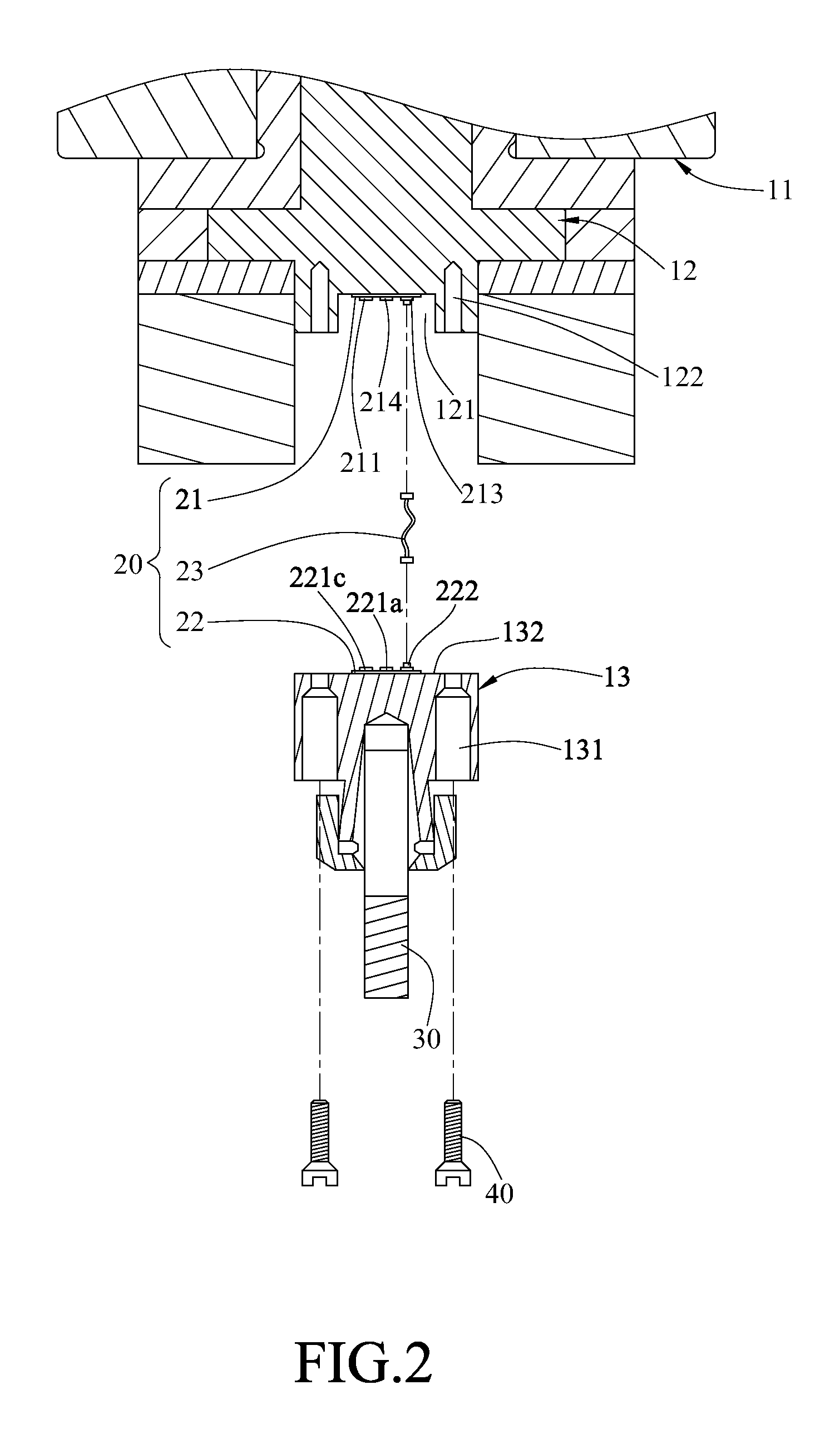
[0017]A machine tool spindle structure capable of monitoring a working state in real time provided by the present invention is used to measure a temperature, a vibration amount, a torque, and other working parameters of the machine tool spindle during a processing process. An external information device receives the working parameters, and displays and analyzes data, so as to give a feedback of the working state of a processing cutter in real time for operators, thereby achieving a good processing quality.

[0018]The machine tool provided by the present invention refers to a drilling machine, a milling machine, a grinding machine, a planning machine, and other machine tools adopting the rotationally cutting movement. The machine tool spindle may be categorized into gear power transmission, belt power transmission, direct power transmission, built-in motor, and other types according to the power source. A bearing of the machine tool spindle may be a rolling bearing, a hydrostatic beari...


PUM


Abstract

A machine tool spindle structure capable of monitoring a working state in real time includes a spindle body, a rotating mandrel, a cutter base, and an internal inspecting device. The cutter base is combined with the rotating mandrel and rotates with the rotating mandrel. The rotating mandrel has a chamber, and the internal inspecting device is disposed in the chamber. Inspecting chips in the internal inspecting device are directly disposed on the cutter base, so as to measure working parameters during a processing process. The working parameters are transmitted to an external information device by a wireless transmission module in the internal inspecting device, thereby accurately giving a feedback of the working state of a processing cutter in real time.

Description

CROSS-REFERENCE TO RELATED APPLICATIONS[0001]This non-provisional application claims priority under 35 U.S.C. §119(a) on Patent Application No(s). 097147558 filed in Taiwan, R.O.C. on Dec. 5, 2008 the entire contents of which are hereby incorporated by reference.BACKGROUND OF THE INVENTION[0002]1. Field of Invention[0003]The present invention relates to a machine tool member, in particular to a machine tool spindle structure having a device for inspecting a working state.[0004]2. Related Art[0005]Machine tools are machinery for manufacturing various machines and processing equipment, and may be categorized into metal cutting machine tools and metal molding machine tools according to functions. The metal cutting machine tools include lathes, drilling machines, milling machines, grinding machines, and planning machines, and the metal molding machine tools include punching machines and shearing machines. A machine tool is composed of several parts, in which in the drilling machine, the...

Claims


Application Information

Patent Timeline
IPC IPC(8): G06F19/00
CPCB23Q17/00B23Q17/09Y10T409/309408Y10T408/16Y10T409/30728B23Q17/0971B23Q17/0985
Inventor TANG, KUO-YUHUANG, CHUN-HUNGKUO, TZU-HSIN
Owner IND TECH RES INST
Why Eureka
Try Eureka