
Robot System

Active Publication Date: 2010-06-10
COMAU SPA
View PDF5 Cites 106 Cited by
  • Summary
  • Abstract
  • Description
  • Claims
  • Application Information

AI Technical Summary

Benefits of technology

[0008]In the light of what is set forth above, the object of the present invention is basically to provide a robot system equipped with a manual guide device that is easy to install, simple to use, and inexpensive to produce, as well as being convenient and fast to interface to a portable programming terminal or teach pendant. The correlated object of the invention is to provide a manual guide device that can be transferred in a simple and fast way from one robot to another, for the purposes of the corresponding programming operations.

Problems solved by technology

In order to follow the TCP closely and make a visual check on positioning thereof, the operator moves continuously around the robot: by so doing, the operator moves evidently also with respect to the origins of the aforesaid reference systems, and this complicates to a certain extent the activity of programming, also in view of the fact that the operator is each time called upon to select the reference system that he wishes to use.
Known devices of this type, generally based upon the use of a force / torque sensor connected to the control unit of the robot or else to the corresponding teach pendant via wired connection, are inconvenient to install, relatively cumbersome and costly, and their modalities of interfacing to the control system of the robot are frequently complex.
These disadvantages also have the consequence of rendering the transferability of the guide device from one robot to another laborious, for example in the cases where a number of robots of one and the same working environment are to be programmed.

Method used


Image

  • Robot System
  • Robot System
  • Robot System

Examples


Embodiment Construction

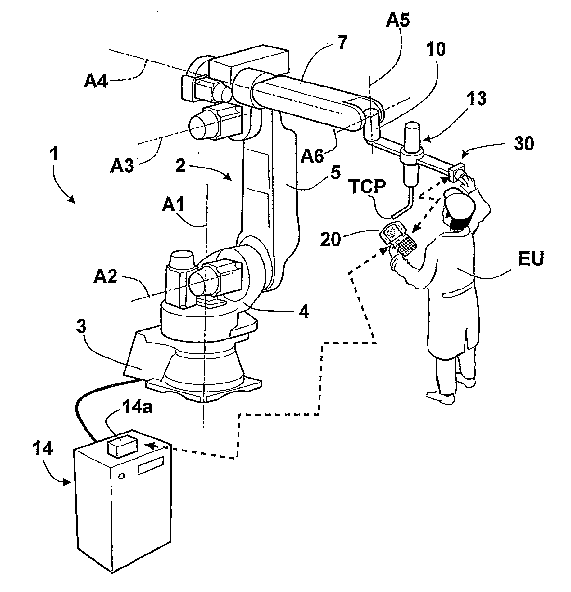
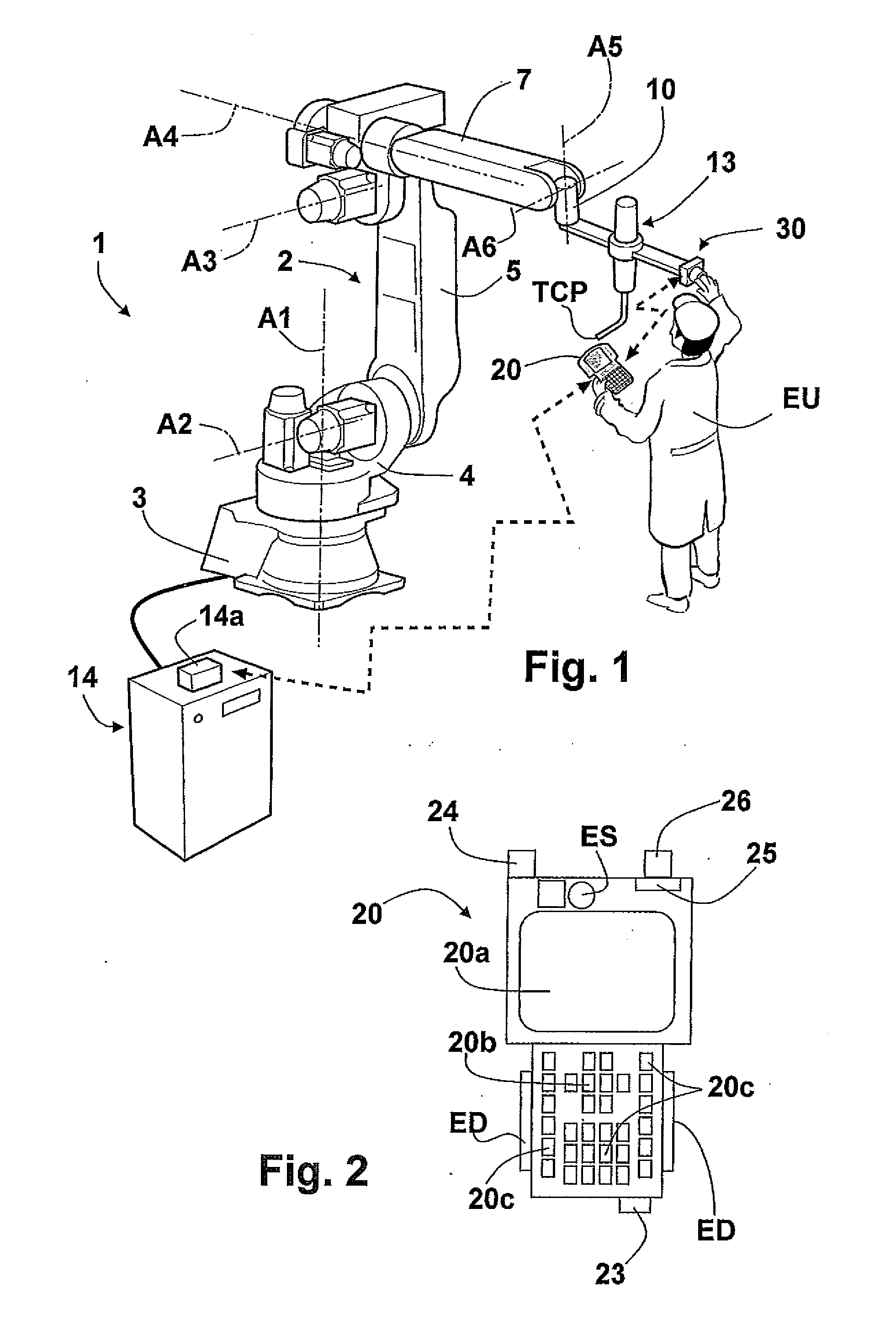
[0017]Represented schematically in FIG. 1 is a robot system according to the invention, comprising a robot 1 having a structure 2 that is movable according to a number of degrees of freedom. In the example illustrated, the robot is an anthropomorphic robot having a base 3 and a column 4 mounted so that it can turn on the base 3 about a first axis A1 directed vertically. Designated by 5 is an arm mounted oscillating on the column 4 about a second axis A2 directed horizontally. Designated by 7 is a forearm mounted on the arm 5 about a third axis A3, which is also directed horizontally. The forearm 7 moreover has the possibility of turning about its axis A4, which consequently constitutes a fourth axis of movement of the robot 1, and is equipped at its end with a wrist 10, mounted for the movement according to two axes A5 and A6. Associated to the terminal flange of the wrist 10 is a tool or end effector, designated by 13, which in the example is represented by a welding torch with cor...


PUM


Abstract

A robot system having a manual guide device connected to the robot in wireless data communication with a portable terminal for use in programming the robot.

Description

FIELD OF THE INVENTION[0001]The present invention relates to industrial robots and has been developed with particular reference being paid to devices used for carrying out the programming or “teaching” of industrial robots.BACKGROUND[0002]The activity of programming of a robot basically consists in teaching the robot the path that a point of its movable structure must repeat automatically in the course of the normal working steps, to execute a certain operation. Said point is typically represented by the so-called “Tool Center Point” (TCP), which identifies in general the position of the active part of the tool mounted on the wrist of the robot, i.e., the part that executes the operation and that is defined by an operator in a convenient way according to the application. For example, in the case of an operation of arc welding, the TCP is located on the tip of the welding torch at the end of the welding wire; in sealing applications, the TCP is instead at a nozzle for outlet of the s...

Claims


Application Information

Patent Timeline
IPC IPC(8): G05B15/00
CPCB25J13/06G05B2219/36162G05B2219/33192G05B19/425
Inventor GERIO, GIAN PAOLOLACHELLO, LUCAROMANELLI, FABRIZIOCICCIARELLO, BRUNOFRACCAROLI, MICHELEMOLINARI TOSATTI, LORENZOPARAZZOLI, DIEGOSCARI, EFTOREDANESI, MAFLEO
Owner COMAU SPA
Learn More