Centralized load management for use in controllably recharging vehicles equipped with electrically powered propulsion systems
- Summary
- Abstract
- Description
- Claims
- Application Information
AI Technical Summary
Benefits of technology
Problems solved by technology
Method used
Image
Examples
utility embodiment
Multi-Utility Embodiment
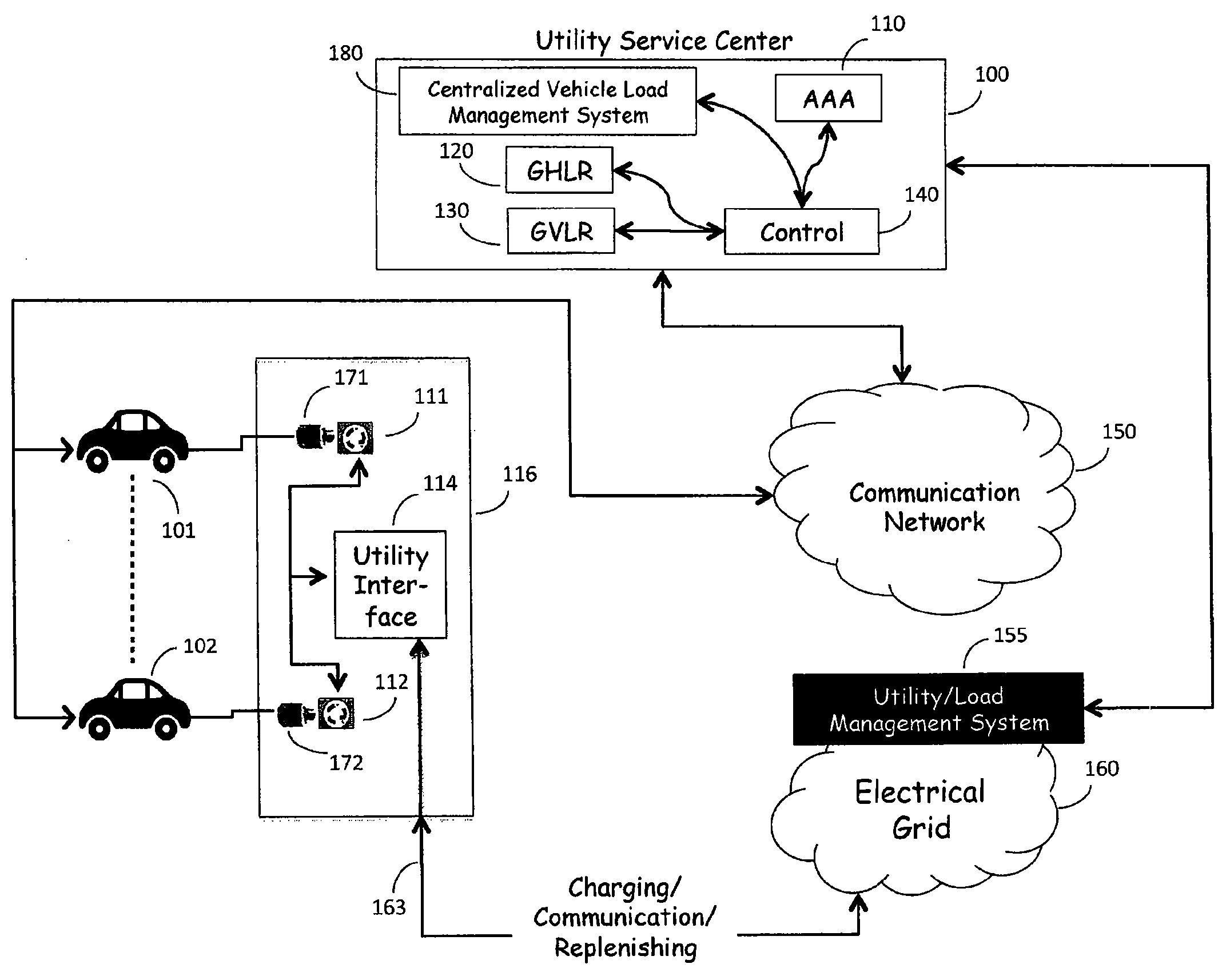
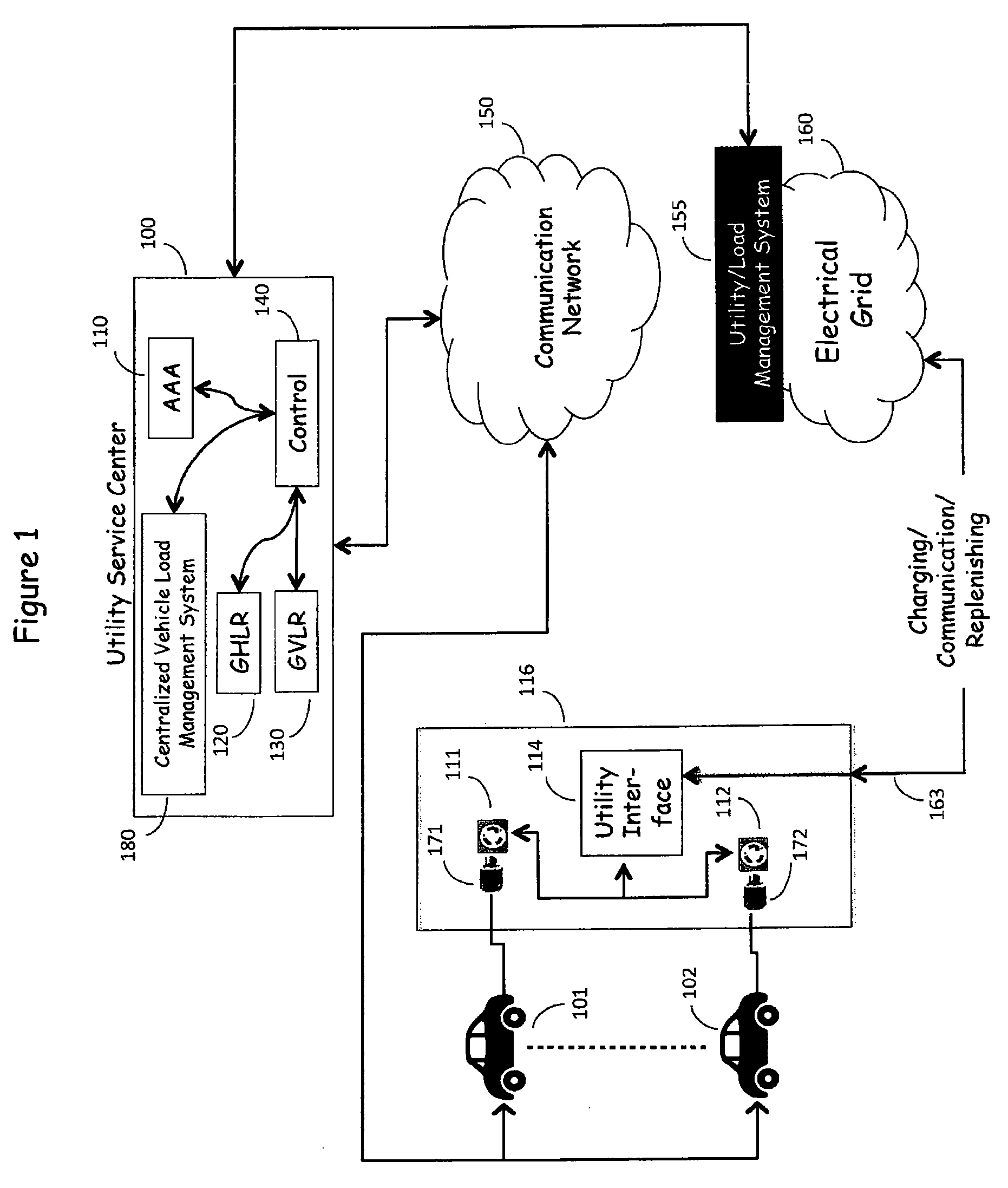
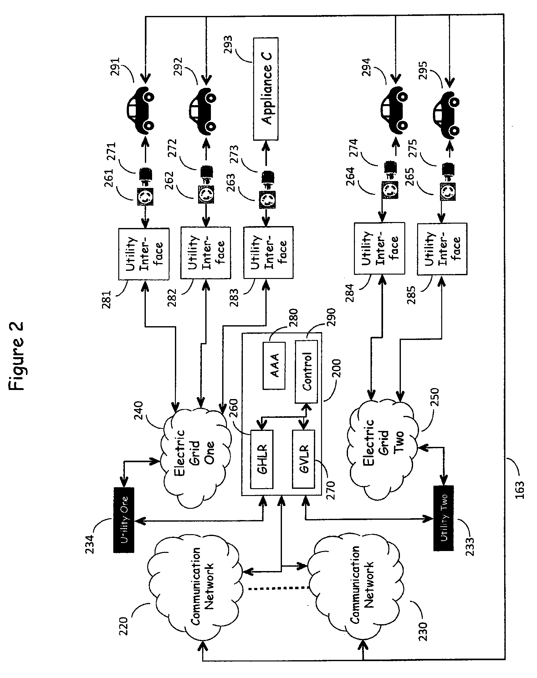
[0044]FIG. 1 is in reality a multidimensional network in which N electric utilities are served by M Electric Power Grids with corresponding communication networks, as shown in FIG. 2. Electric Power Grids 240, 250 shown in FIG. 2 represent the source of electric power as provided by multiple utility companies which serve a wide geographic area and provide electric power to a multitude of customers via utility interfaces 281-285. The utility interfaces 281-285 serve to measure the energy consumption by the various outlet connected loads, such as Vehicles 291-295. These elements represent the existing, present day electric power delivery infrastructure as described above. Electric power traditionally flows from the Electric Power Grid 240, 250 to the utility interfaces 281-285 via the Electric Power Grid and thence to the customer's loads—Vehicles 291-295 via plug 271-275-outlet 261-265 combinations, but power also can flow in the reverse direction, from the ve...
PUM
 Abstract
Description
Claims
Application Information
 - R&D
- Intellectual Property
- Life Sciences
- Materials
- Tech Scout
- Unparalleled Data Quality
- Higher Quality Content
- 60% Fewer Hallucinations
Browse by: Latest US Patents, China's latest patents, Technical Efficacy Thesaurus, Application Domain, Technology Topic, Popular Technical Reports.
© 2025 PatSnap. All rights reserved.Legal|Privacy policy|Modern Slavery Act Transparency Statement|Sitemap|About US| Contact US: help@patsnap.com


