
Data center cooling energy recovery system

a data center and energy recovery technology, applied in the field of cooling of computing systems, can solve the problems of affecting the structural exacerbate the heat dissipation problem, and damage the structure and data integrity of the computer system and even the data center as a whol

Inactive Publication Date: 2010-06-17
IBM CORP
View PDF7 Cites 24 Cited by
  • Summary
  • Abstract
  • Description
  • Claims
  • Application Information

AI Technical Summary

Problems solved by technology

Traditionally, as the size and complex nature of a business grows, its computing needs are greatly increased.
Because of cost concerns, however, data centers are designed to house a maximum number of units, including the computer systems and their associated components, in a tight foot print.
The ever growing number of heat generating components inside the computer units further exacerbate the heat dissipation issues.
These issues if not dealt with adequately can harm the structural and data integrity of the computer system and even the data center as a whole.
Cooling of data centers has become a significant cost of operation for businesses.
Unfortunately, with rising energy costs, the cost of maintaining data centers have become prohibitive.

Method used


Image

  • Data center cooling energy recovery system
  • Data center cooling energy recovery system
  • Data center cooling energy recovery system

Examples


Embodiment Construction

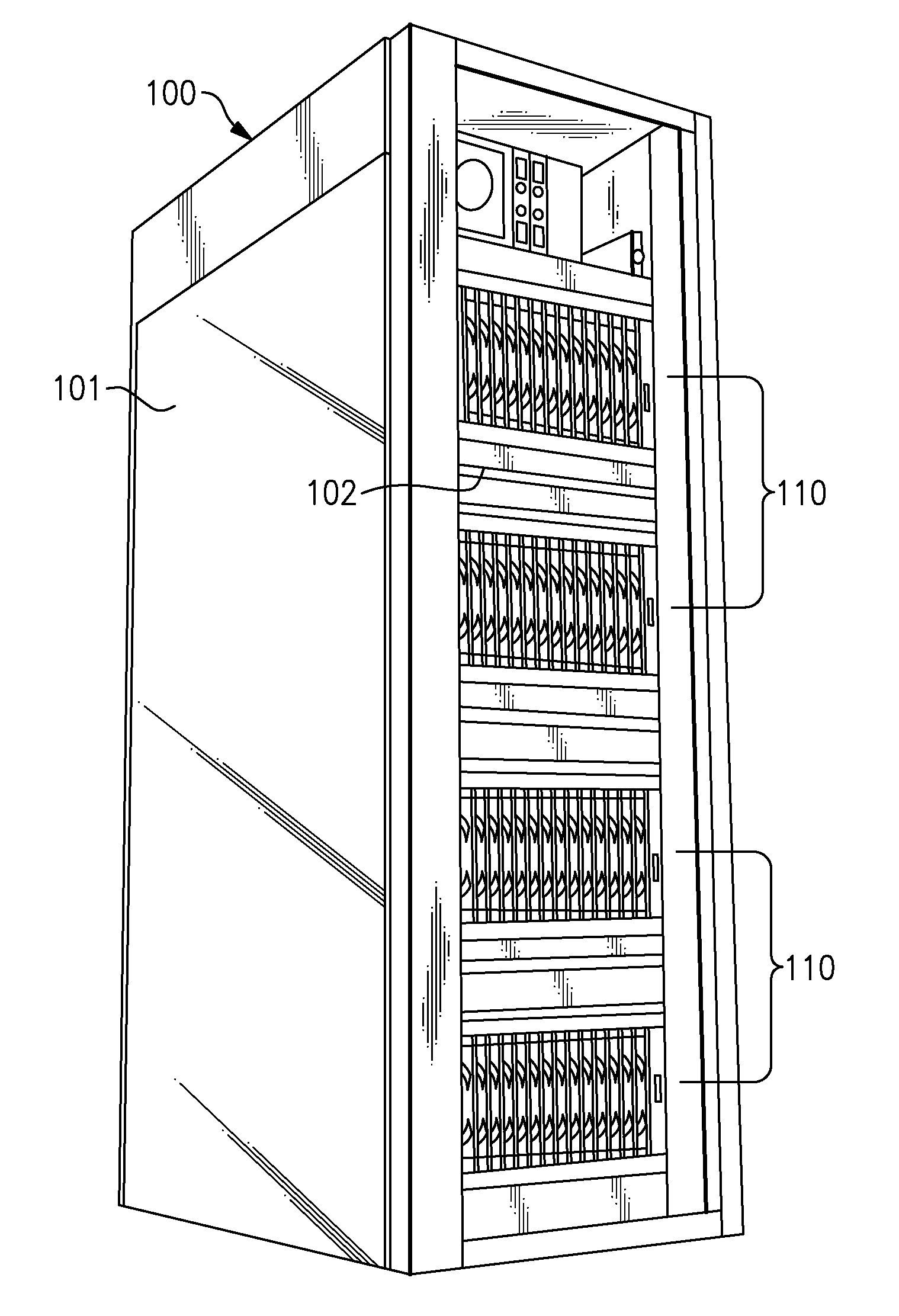
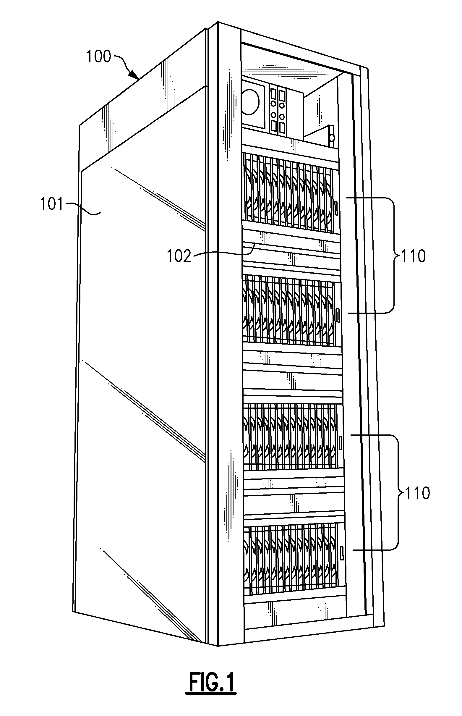
[0015]FIG. 1 is a perspective view illustration of a computer environment comprising of a housing 100, having a frame 102, preferably with a rack or cage like structure as shown. The housing 100 can also incorporate full or partial doors or covers such as referenced by numerals 101.

[0016]It should be noted that as used herein, the term computer or electronic rack 102, hereinafter will be used for ease of reference but can be construed to include any housing, frame, rack, compartment, blade server system or other structural arrangements including any that may incorporate doors and / or covers. In addition, the computer rack 102 can be either a stand alone computer processor or a sophisticated system, having high, mid or low end processing capability. The electronic rack 102 may also comprise a stack of electronic system chassis or multi-blade center systems 110, as well as supporting power supplies, networking equipment and other similar and necessary components, not individually illus...


PUM


Abstract

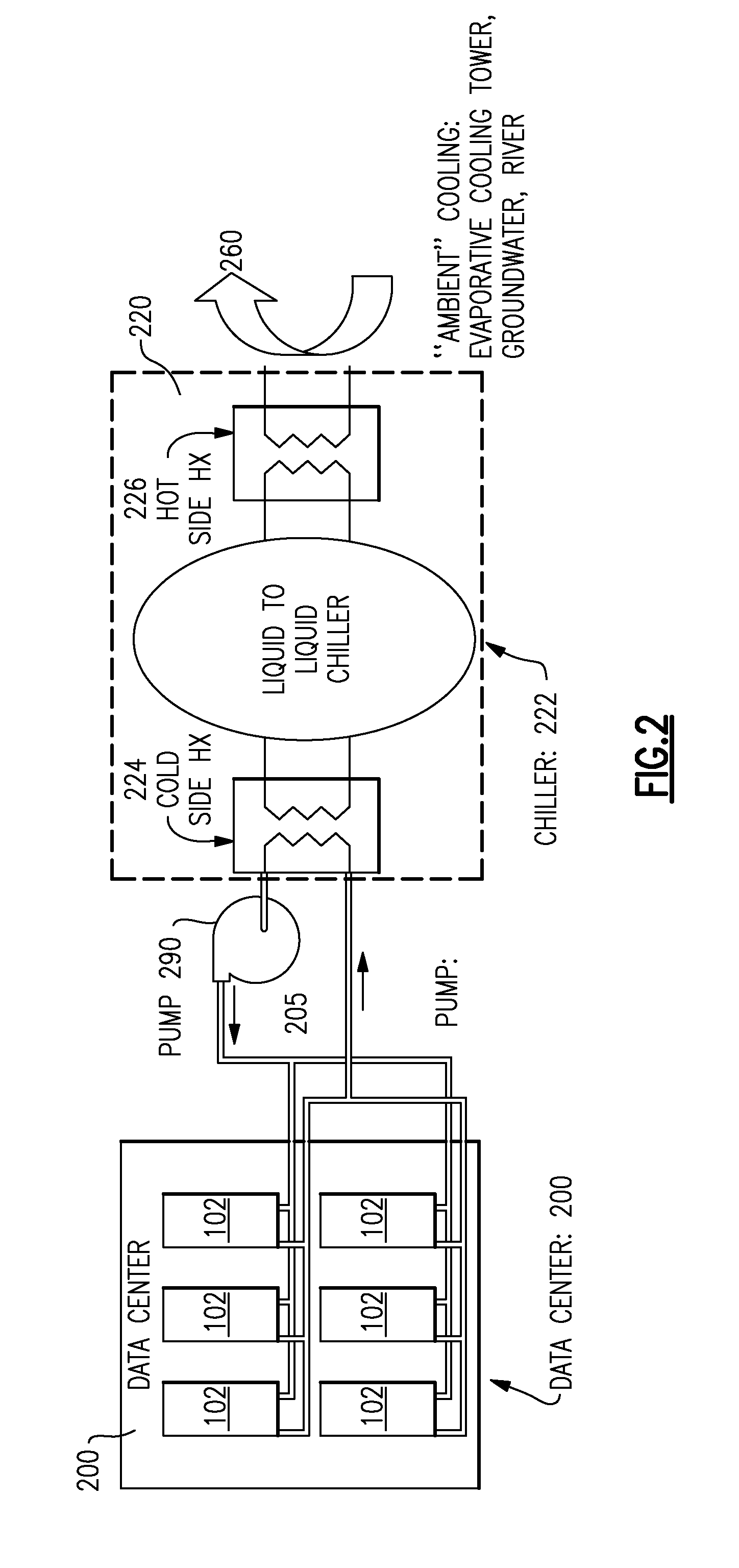
A method and associated system is provided for cooling of a data center. The method includes providing coolant to multiple cooling elements in the data center using a heat pump refrigeration cycle to cool the coolant and provide a high temperature at the condenser. This allows the reclaiming of at least a portion of the heat removed from the refrigeration cycle using a heat engine. The engine is disposed between the refrigeration condenser and the ambient environment or cooling medium.

Description

BACKGROUND OF THE INVENTION[0001]1. Field of the Invention[0002]This invention relates to cooling of computing systems environments and more particularly to cooling of data centers housing a variety of heat generating components such as large computing systems and servers.[0003]2. Description of Background[0004]Businesses today have grown increasingly dependent on the processing power of computer systems. Traditionally, as the size and complex nature of a business grows, its computing needs are greatly increased. Many large businesses require a number of sophisticated computers such as servers to provide for their computing needs. These computing needs require fast and continuous operation of all systems that at times have to be in communication with one another.[0005]It is often more convenient to house a variety of computer systems in a common facility known as a data center. Data centers also house associated computing components such as such as telecommunication and storage syst...

Claims


Application Information

Patent Timeline
IPC IPC(8): F25D15/00F25B39/02
CPCF02G2254/00H05K7/2079F25B27/02
Inventor CAMPBELL, LEVI A.CHU, RICHARD C.ELLSWORTH, JR., MICHAEL J.IYENGAR, MADHUSUDAN K.SIMONS, ROBERT E.
Owner IBM CORP
Learn More