Back illuminated sensor with low crosstalk

a backside and sensor technology, applied in the field of image sensors, can solve the problems of linear improvement of image quality, affecting crosstalk performance, and reducing the size of the pixel for a backside configuration, and achieve the effect of improving crosstalk performan

Active Publication Date: 2010-06-17
OMNIVISION TECH INC
View PDF3 Cites 83 Cited by
  • Summary
  • Abstract
  • Description
  • Claims
  • Application Information

AI Technical Summary

Benefits of technology

[0014]The present invention has the advantage of providing an image sensor with improved cross talk performance.

Problems solved by technology

However, as illustrated in FIG. 4, reducing the size of the pixel for a backside configuration does not improve MTF performance linearly.
More importantly, for color parts, this can produce color mixing between pixels, and thus degrade image quality.

Method used


Image

  • Back illuminated sensor with low crosstalk
  • Back illuminated sensor with low crosstalk
  • Back illuminated sensor with low crosstalk

Examples


Embodiment Construction

[0026]In the following Detailed Description, reference is made to the accompanying drawings, which form a part hereof, and in which is shown by way of illustration specific embodiments in which the invention may be practiced. In this regard, directional terminology, such as “top,”“bottom,”“front,”“back,”“leading,”“trailing,” etc., is used with reference to the orientation of the Figure(s) being described. Because components of embodiments of the present invention can be positioned in a number of different orientations, the directional terminology is used for purposes of illustration and is in no way limiting. It is to be understood that other embodiments may be utilized and structural or logical changes may be made without departing from the scope of the present invention. The following detailed description, therefore, is not to be taken in a limiting sense, and the scope of the present invention is defined by the appended claims.

[0027]FIG. 6 illustrates a cross-sectional view of a ...


PUM


Abstract

A back-illuminated image sensor includes a sensor layer having a frontside and a backside opposite the frontside. An insulating layer is situated adjacent the backside and a circuit layer is adjacent the frontside. A plurality of photodetectors of a first type conductivity convert light incident on the backside into photo-generated charges. The photodetectors are disposed in the sensor layer adjacent the frontside. A region of a second type conductivity is formed in at least a portion of the sensor layer adjacent the frontside and is connected to a voltage terminal for biasing the second type conductivity region at a predetermined voltage. A well of the second type conductivity is formed in the sensor layer adjacent the backside. Trench isolations in the sensor layer start at the frontside and extend beyond the depletion region of the photodiodes.

Description

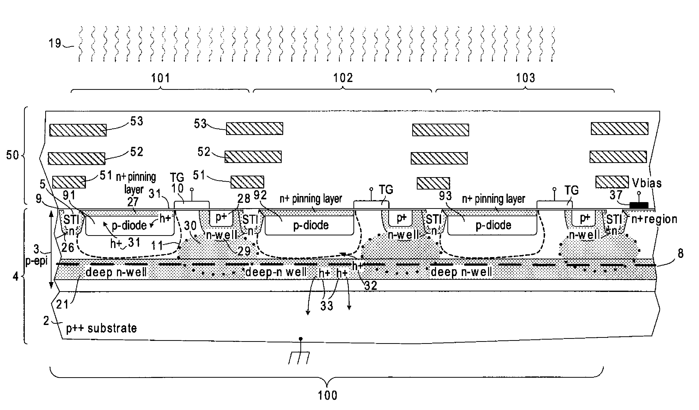
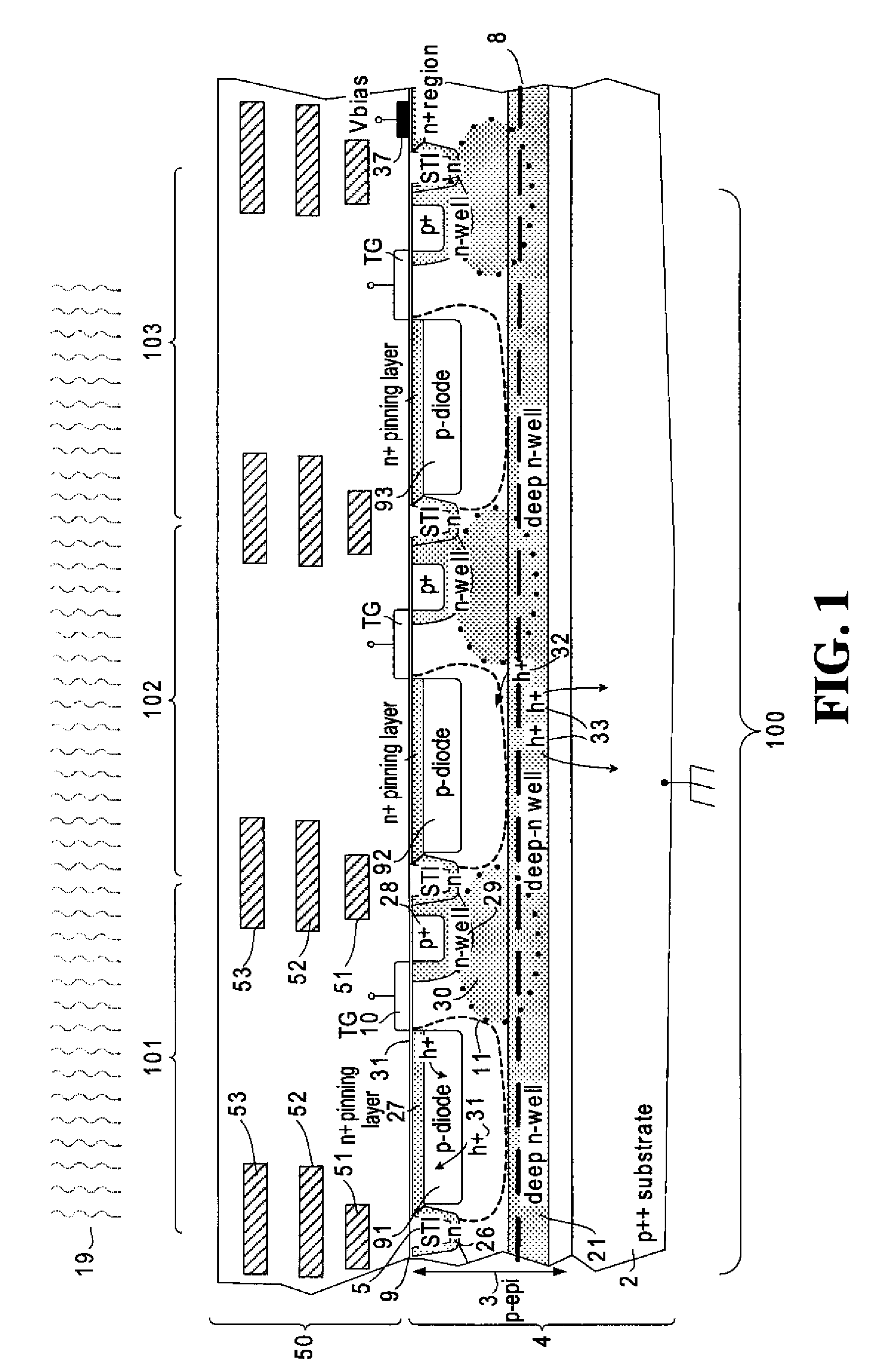
FIELD OF THE INVENTION[0001]The present invention relates generally to image sensors, and more particularly to back-illuminated image sensors.BACKGROUND OF THE INVENTION[0002]An electronic image sensor captures images using light-sensitive photodetectors that convert incident light into electrical signals. Image sensors are generally classified as either front-illuminated image sensors or back-illuminated image sensors. FIG. 1 is a simplified cross-section of a front-illuminated image sensor through three pixels 101, 102, 103. The illustrated image sensor 100 is a pmos image sensor, which includes pixels 101, 102, 103 formed within a p++ substrate 2 on p− epi silicon layer 3. Photodetectors 91, 92, 93 are formed within this sensor layer 4. An n-type pinning layer 27 is formed over each photodetector 91, 92, 93. One or more shallow trench isolation (STI) regions 5 are formed within each pixel 101, 102, 103. A different n-type pinning layer 26 lines the STI trench, the purpose of whic...

Claims


Application Information

Patent Timeline
Patent Type & Authority Applications(United States)
IPC IPC(8): H01L31/0232H01L31/08H01L31/18
CPCH01L27/1463H01L27/1464H01L27/14689H01L27/14656
Inventor MCCARTEN, JOHN P.SUMMA, JOSEPH R.TIVARUS, CRISTIAN A.
Owner OMNIVISION TECH INC
Why Eureka
Try Eureka