Solid state lighting

a technology of solid state lighting and light source, applied in the direction of semiconductor devices for light sources, light and heating equipment, fixed installations, etc., can solve the problems of reducing optical output, shortened useful life, and affecting the performance of short-term and long-term leds, so as to prolong the life of leds used

Inactive Publication Date: 2010-06-17
VETROVEC JAN
View PDF3 Cites 15 Cited by
  • Summary
  • Abstract
  • Description
  • Claims
  • Application Information

AI Technical Summary

Benefits of technology

[0012]It is another object of the invention to provide improved means for cooling LED used in SSL downli

Problems solved by technology

Excessive temperature directly affects both short-term and long-term LED performance.
The short-term (reversible) effects are color shift and reduced light output while the long-term effect is reduced optical output (also known as “accelerated lumen depreciation”) and thus shortened useful life.
The primary cause of lumen depreciation is heat generated at the LED junction.
If the LED system design has inadequate heat sinking or other means of removing the heat, the device temperature will rise, resulting in lower light output.
The challenge in cooling LED down light is the transport of was

Method used


Image

  • Solid state lighting
  • Solid state lighting
  • Solid state lighting

Examples


Embodiment Construction

[0020]Selected embodiments of the present invention will now be explained with reference to drawings. In the drawings, identical components are provided with identical reference symbols. It will be apparent to those skilled in the art from this disclosure that the following descriptions of the embodiments of the present invention are merely exemplary in nature and are in no way intended to limit the invention, its application, or uses.

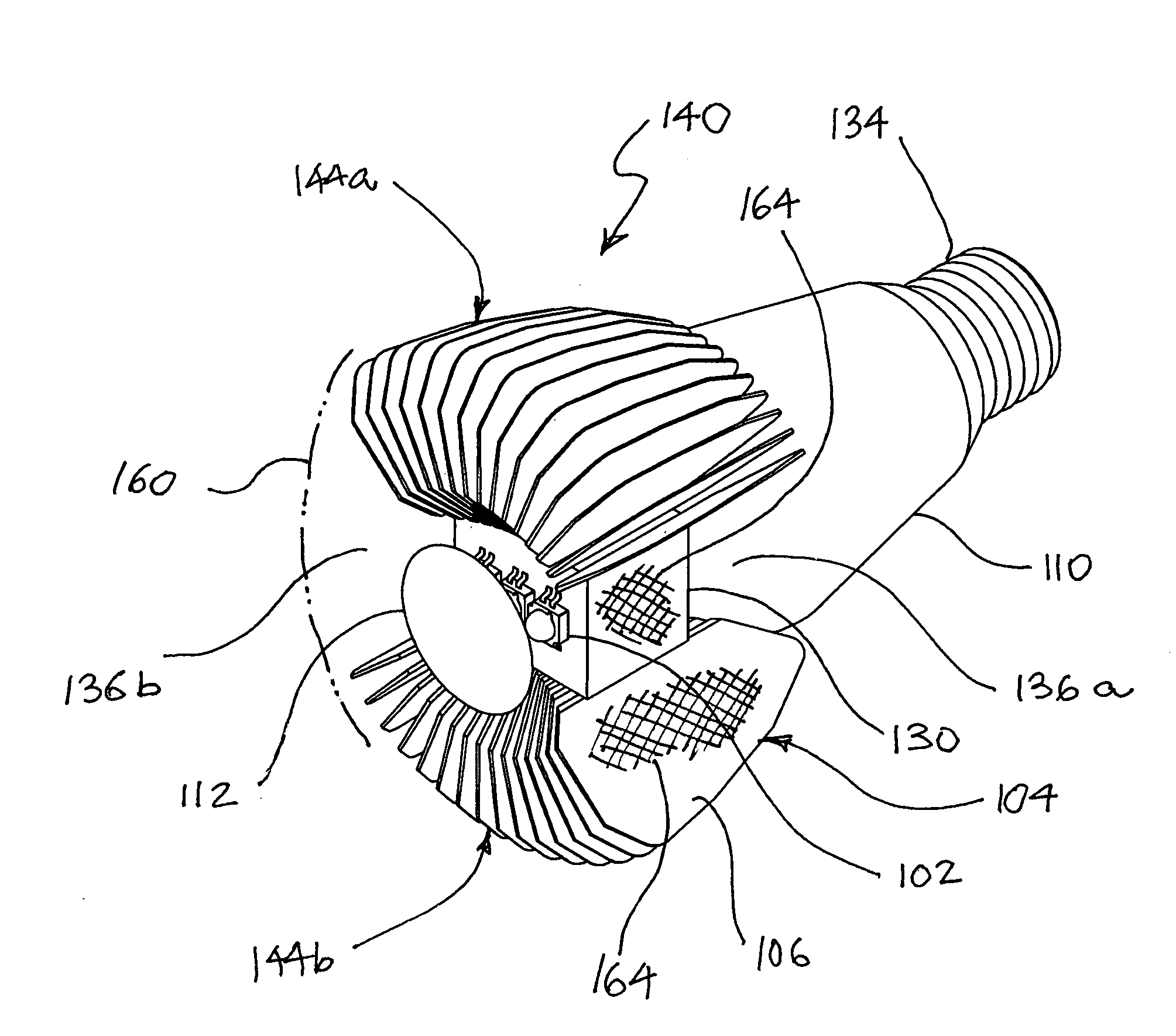
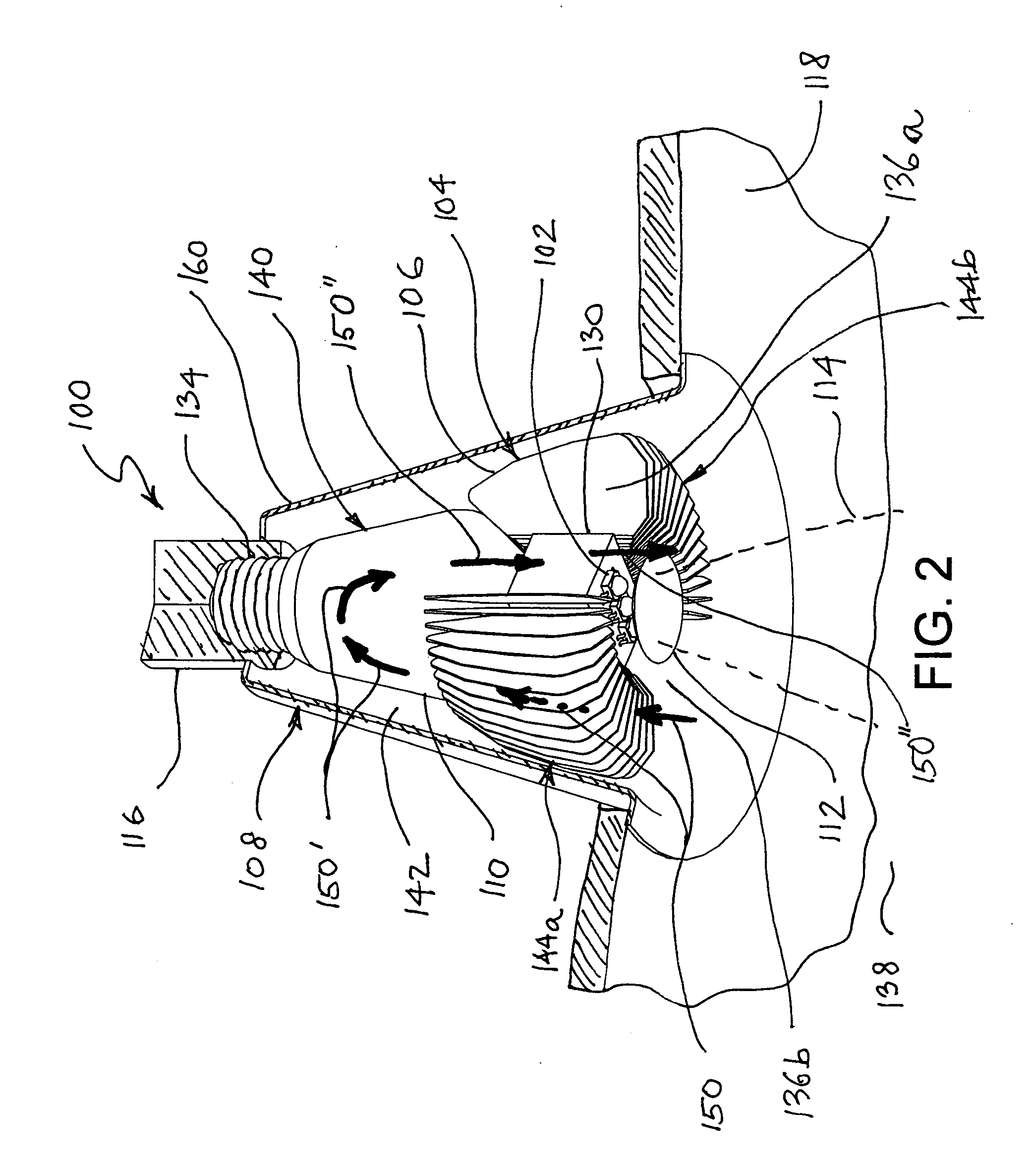
[0021]Referring now to FIG. 2, there is shown an isometric view of SSL fixture 100 in accordance with one preferred embodiment of the subject invention. The SSL fixture 100 comprises a luminaire 108, and an SSL lamp 140. The luminaire 108 may be a conventional recessed light luminaire and it may be installed in a ceiling panel 118. Typically, a recessed light luminaire is adapted for dissipation of waste heat received from a lamp bulb to the space above the ceiling panel 118. The luminaire 108 may further comprise a socket 116 and a luminaire shell 160...


PUM


Abstract

The present invention provides a solid-state lighting fixture and lamp for down light for use in applications especially in recessed lighting. In particular, the lamp of the subject invention may be configured as a direct screw-in replacement for common R-30 style incandescent flood lamp and it may be used existing luminaires. In one preferred embodiment of the present invention, a lamp mounted in a recessed light luminaire for down lighting has one or more light emitting diodes (LEDs) that are thermally coupled to a heat sink having fins for cooling by ambient air. The fins are configured so that air warmed by the fins can rise inside the luminaire and transfer its heat to it. Air cooled by the luminaire is allowed to sink and may flow out of the luminaire via a gap between the heat sink and the luminaire. Fresh cooler air may be drawn in between the fins to replace out-flowing air. This process of heating and cooling of air established a natural convection flow. Natural convective air flow allows for efficient thermal communication between the heat sink and the luminaire, thereby allowing for lower LED junction temperature and longer LED lifetime.

Description

CROSS-REFERENCE TO RELATED APPLICATIONS[0001]This application claims priority from U.S. provisional patent application U.S. Ser. No. 61 / 200,407, filed on Nov. 25, 2008, the entire contents of which are hereby expressly incorporated by reference.FIELD OF THE INVENTION[0002]This invention relates generally to solid-state lighting and more specifically to removal of waste heat from electronic devices.BACKGROUND OF THE INVENTION[0003]The invention is for a lighting fixture and lamp using a solid-state light sources such as a light emitting diode (LED) for generation of visible light.[0004]Solid-state lighting (SSL) using light emitting diode (LED) is a new generation light source for general illumination. In particular, LEDs offer much higher energy efficiency over traditional incandescent light sources such as traditional light bulbs. All light sources convert electric power into radiant energy and heat in various proportions. Incandescent lamps emit primarily infrared (IR), with a sma...

Claims


Application Information

Patent Timeline
IPC IPC(8): H01J61/52
CPCF21K9/00F21S8/02F21V29/004F21V29/83F21V29/71F21V29/773F21Y2101/02F21Y2115/10F21K9/233
Inventor VETROVEC, JAN
Owner VETROVEC JAN
Why Eureka
Try Eureka