Surface mount type power inductor

Inactive Publication Date: 2010-06-17
TODA ISU
View PDF4 Cites 20 Cited by
  • Summary
  • Abstract
  • Description
  • Claims
  • Application Information

AI Technical Summary

Benefits of technology

[0008]Another object of the present invention is to provide a surface mount type power inductor which has a coil wound a low number o

Problems solved by technology

Particularly, as central processing units (CPUs) for use in personal computers have been being directed toward high capacity and high speed, their p

Method used


Image

  • Surface mount type power inductor
  • Surface mount type power inductor
  • Surface mount type power inductor

Examples


Embodiment Construction

[0017]Herein below, a preferred embodiment of the present device will be described in detail with reference to the accompanying drawings. In the following description, where an explanation of some conventional function or conventional construction would impede the comprehension of the gist of the present device, the explanation may be deemed unnecessary.

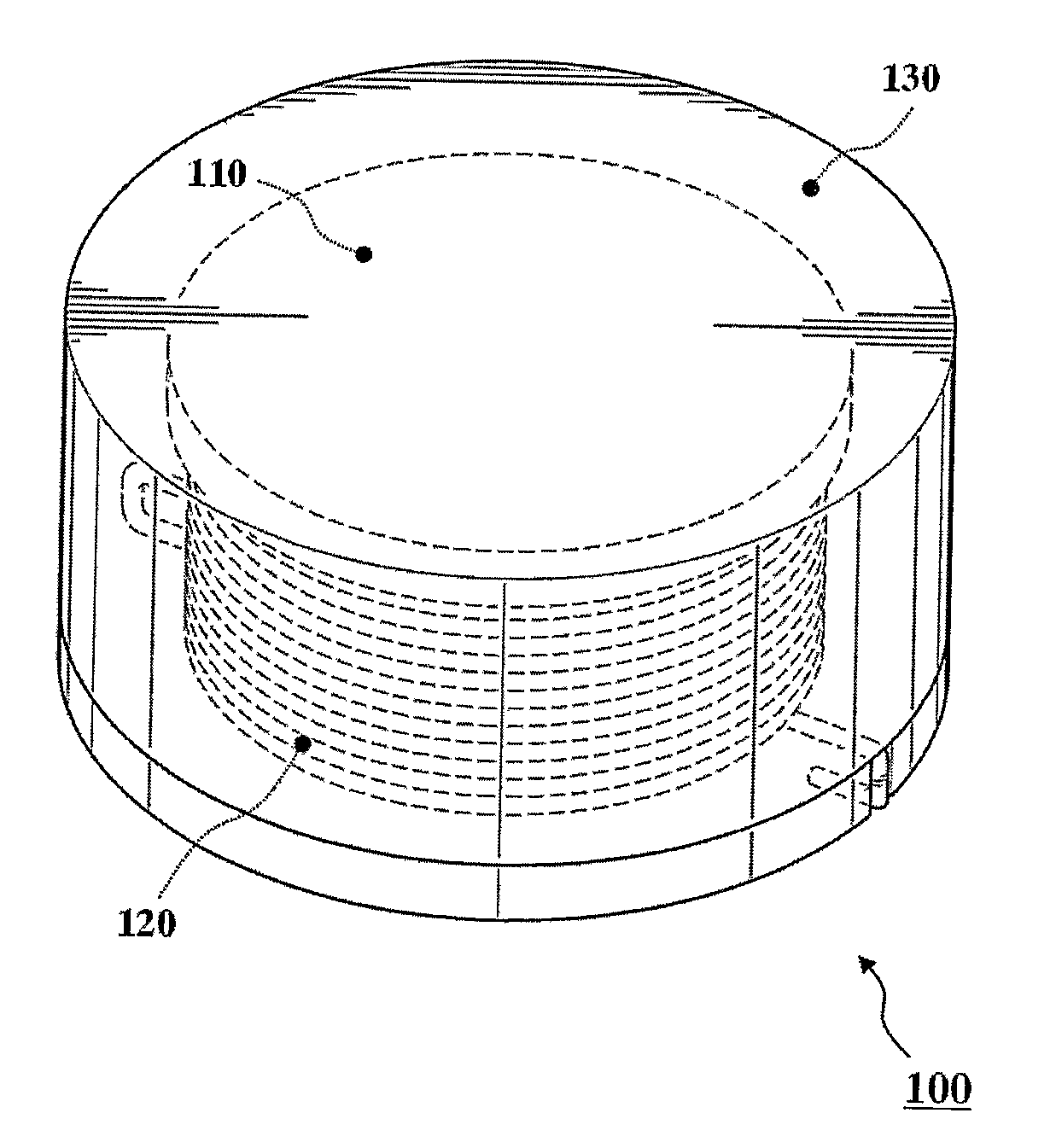
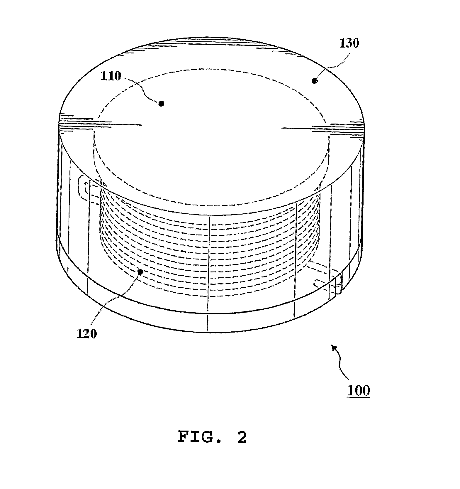
[0018]With reference to FIG. 2, a surface mount type power inductor (hereinafter referred to as “inductor”) 100 according to the present invention is shown. The inductor 100 comprises, as shown in FIG. 2, an inner core 110, a coil 120 wound in a predetermined number of turns around the inner core, and an outer magnetic capsule 130 covering the coil-wound inner core.

[0019]The inner core 110, made from ferrite or magnetic metal, may be formed into a circular drum type shown in FIG. 3a, a square drum type shown in FIG. 3b, a T type (not shown), or an I type (not shown).

[0020]The coil 120, as shown in FIGS. 4a and 4b, is wound a predeter...


PUM


Abstract

Disclosed herein is a surface mount type power inductor which has an outer magnetic capsule integrated with a coil-wound inner core, and which thus has no air gap between the outer magnetic capsule and the inner core, and can maintain a large inductance L in a high current condition. In the inductor, a coil is wound a predetermined number of turns around the inner core formed from ferrite or magnetic metal. An outer magnetic capsule, molded from a magnetic powder, an insulation filler, a binder, and a lubricant, is provided to cover the inner core and the coil.

Description

TECHNICAL FIELD[0001]The present invention relates to a surface mount type power inductor.BACKGROUND ART[0002]With the emphasis of development of various electronic appliances towards slimness and high performance, power circuits for supplying power are also designed not only for high capacity but also for slimness and shortness. Particularly, as central processing units (CPUs) for use in personal computers have been being directed toward high capacity and high speed, their power consumption increasingly grows. In order to satisfy this requirement, power circuits are adapted predominantly to function as a switching regulator type rather than a conventional linear regulator type.[0003]A power inductor, which is usually adopted for a power circuit, has a double core structure consisting, as shown in FIG. 1, of an inner core 10 around which a coil is wound a predetermined number of turns, and an outer core 20 encapsulating the inner core.[0004]Between the inner core and the outer core ...

Claims


Application Information

Patent Timeline
IPC IPC(8): H01F17/04
CPCH01F3/10H01F17/045H01F2017/048H01F27/292H01F27/027H01F27/24H01F3/14
Inventor SHIN, JAE YOUNGSONG, BYUNG MOOLEE, SANG KYUNG
Owner TODA ISU
Why Eureka
Try Eureka