
Power feedback device

a feedback device and power technology, applied in the direction of fixed transformers, wind energy generation, transformers, etc., can solve the problems of increasing the volume and cost of the generator, the inability to maintain the output voltage and current, and the greatly reduced cost and volume of the converter, so as to improve the waveform coefficient of current, increase the power factor and the utilization of the device, and reduce the power factor

Active Publication Date: 2010-06-17
NOVTIUM (BEIJING) SMART ENERGY TECH CO LTD
View PDF6 Cites 4 Cited by
  • Summary
  • Abstract
  • Description
  • Claims
  • Application Information

AI Technical Summary

Benefits of technology

[0006]The objective of the present invention is to provide a power feedback device so as to overcome the disadvantages in the prior art of serious harmonic pollution and low power factor, to improve the waveform coefficients of the current from power generation device, to increase the power factor and the utilization of the device, and to lower harmonic content, characterized by advantages of low cost, high reliability and high conversion efficiency.
[0019]The power feedback device according to the present invention improves the waveform coefficients of the current of the power generation device and increases the power factors and the utilization rate of the device by respectively power converting any two phases among the three phases or multiple phases of AC generated by the power generation device. The multiple paths of windings at the secondary side of the isolating transformer match the device with power networks of different voltage levels, thereby improving the waveform coefficients of the current fed back to the power networks and lowering harmonic component, and the device has advantages of high conversion efficiency, reliable operation, long service life, easy for popularization and maintenance.

Problems solved by technology

Common features of power generation systems of such new resources lie in dispersive power generation devices, small unit capacity, wide distribution area, and unstable output voltage and current.
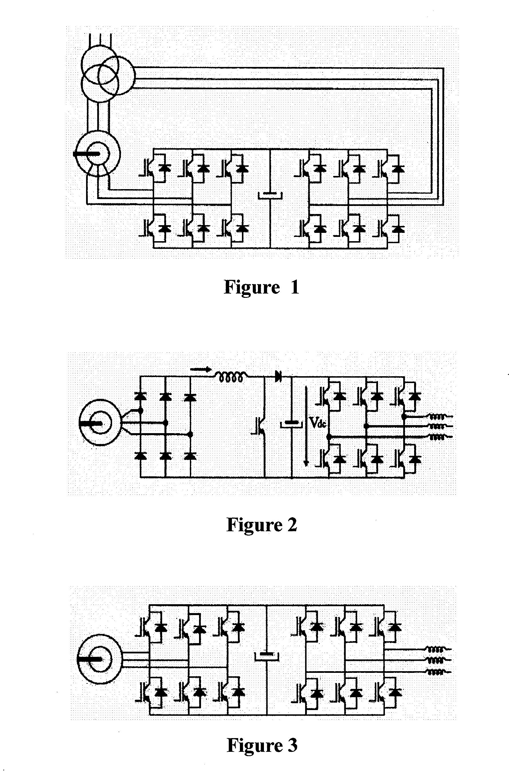
Thus, the cost and volume of the converter is greatly decreased, while this solution has disadvantages that the volume and cost of the generator is increased as wound rotor is adopted in the generator and AC excitation are conducted via slip ring, and the generator has a high failure rate and maintenance fee due to the use of the slip ring.
As shown in FIG. 4, a semi-controllable power semiconductor device thyristor is adopted in this system, although this solution has low cost, it has serious harmonic pollution at the network side, and the power factor is low, and harmonic treatment device need to be added additionally, which raises the overall cost.

Method used


Image

  • Power feedback device
  • Power feedback device
  • Power feedback device

Examples


embodiment 1

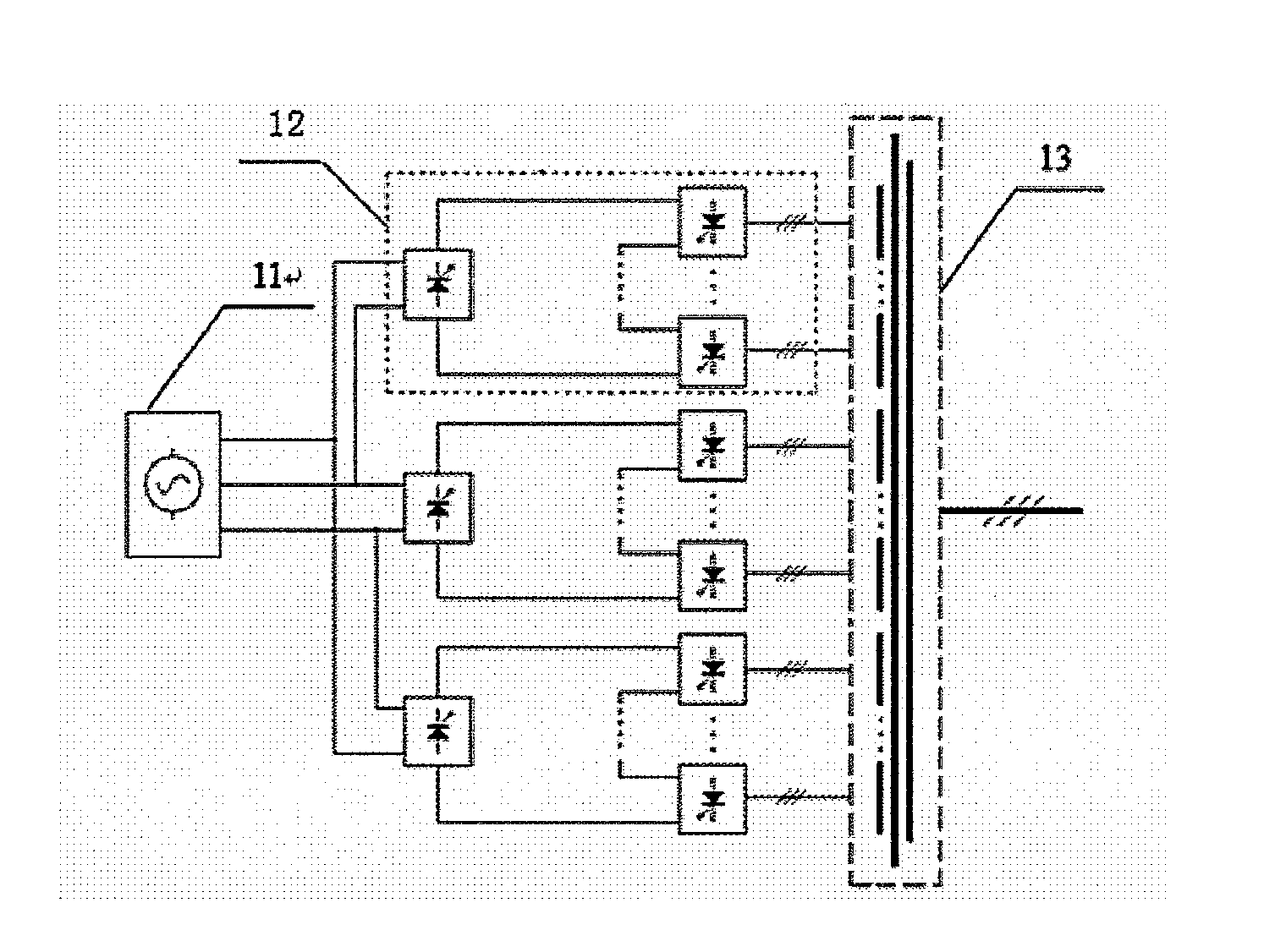
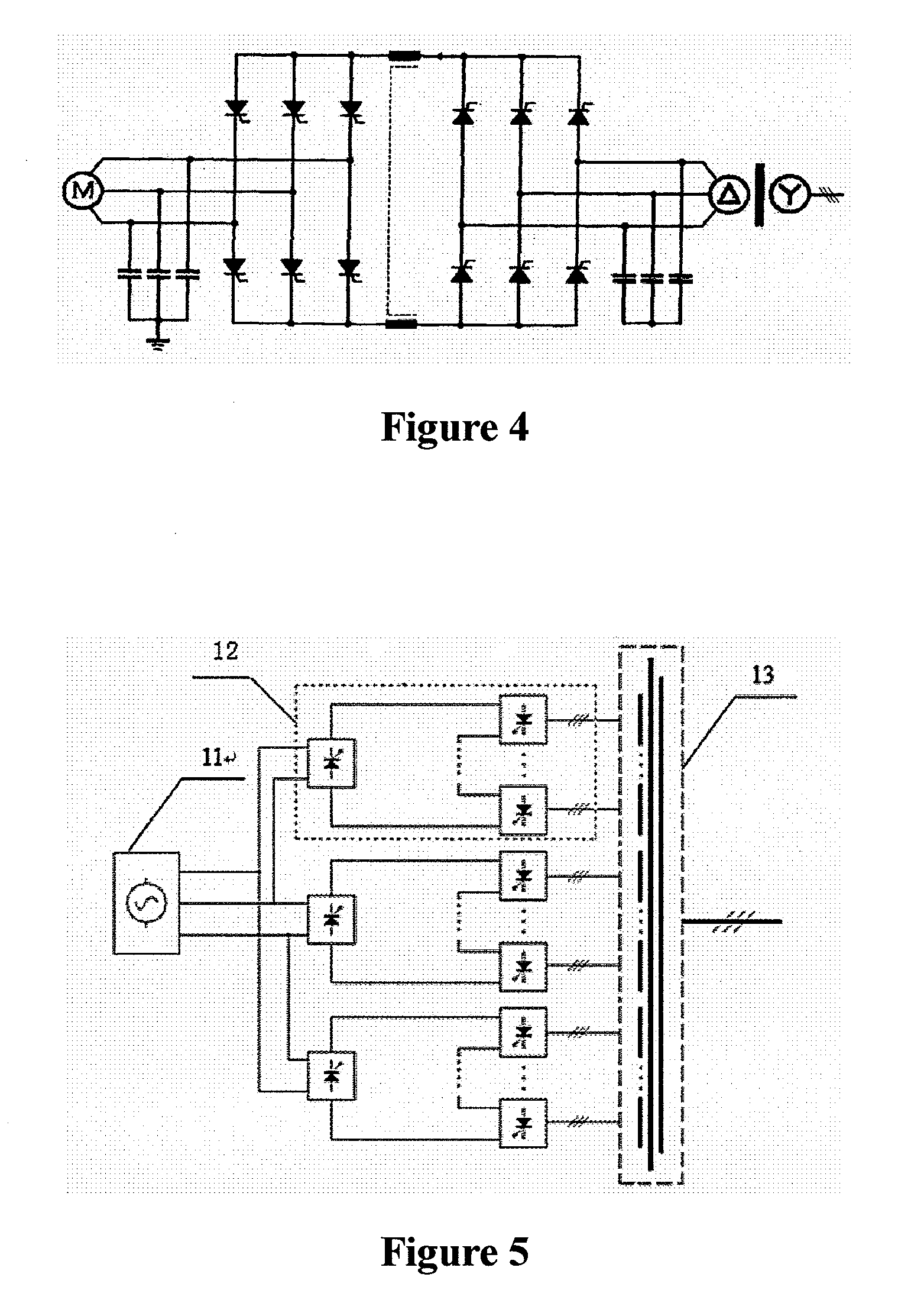
[0038]FIG. 5 illustrates the principle of embodiment 1 of the power feedback device according to the present invention. As shown in FIG. 5, the power feedback device includes: an AC input power source 11, a plurality of power converting units 12 and an isolating transformer 13; wherein the AC input power source 11 is three-phase or multi-phase AC or three-phase or multi-phase AC in which the output terminal is connected in series with an inductor, for generating power; the input terminals of the a plurality of power converting units 12 are respectively connected with two terminals of the AC input power source 11, for power converting the two phases of AC generated by the AC input power source 11 respectively; the primary side of the isolating transformer 13 is a three-phase winding and connected with a power network, and the secondary side of the isolating transformer 13 is a multi-path three-phase winding and connected with the output terminals of the a plurality of power convertin...

embodiment 2

[0041]FIG. 9 illustrates the principle of embodiment 2 of the power feedback device according to the present invention. As shown in FIG. 9, the power feedback device includes: an AC input power source 11, a plurality of power converting units 12, and an isolating transformer 13; and the device may further include: at least one Pulse Width Modulation (short for PWM hereinafter) three-phase inverter bridge circuit 14 consisting of a filtering capacitor and a fully controlled power semiconductor device, the output terminal of the PWM three-phase inverter bridge circuit being connected in series with the inductor and then being connected with the three-phase winding of the secondary side of the isolating transformer 13, or being connected with the output terminals of the power converting units 12, or being connected with the output terminals of the power converting units 12 via an isolating capacitor, or being connected with the three-phase winding of the secondary side of the isolating...


PUM


Abstract

The present invention relates to a power feedback device, including: an AC input power source, which is three-phase or multi-phase AC, or three-phase or multi-phase AC in which the output terminal is connected in series with an inductor, for generating power; a plurality of power converting units, the input terminals of which are respectively connected with two phases of the AC input power source, for power converting the two phases of AC generated by the AC input power source respectively; an isolating transformer, the primary side of which is a three-phase winding and connected with a power network, the secondary side of which is multi-path of three-phase windings and connected with the output terminals of the plurality of power converting units, for feeding the AC converted by the plurality of power converting units back to the power network. The power feedback device according to the present invention can improve the waveform coefficients of the current of the power generation device, and increase the power factors and the utilization rate of the device, and also, the device matches power networks of different voltage levels, thereby improving the waveform coefficients of the current fed back to the power networks and lowering harmonic component.

Description

[0001]The present application claims the priority of the Chinese patent application No. 200810084692.7 filed with the Chinese Patent Office on Mar. 18, 2008 entitled “A Power Feedback Device”, the entire contents of which are incorporated herein by reference.FIELD OF THE INVENTION[0002]The present invention relates to power electronic technologies, particularly to a power feedback device.BACKGROUND OF THE INVENTION[0003]People are paying more and more attention to the use of the power generation of renewable resources such as wind power generation, solar power generation, and tidal power generation. Common features of power generation systems of such new resources lie in dispersive power generation devices, small unit capacity, wide distribution area, and unstable output voltage and current. It has been currently an urgent problem to be solved in our country and worldwide on how to feed the power generated by the power generation devices of such renewable resources back to power net...

Claims


Application Information

Patent Timeline
IPC IPC(8): H02M5/458
CPCH01F30/04H02M5/4505H02M2001/0074H02P13/06H02J3/382H02J3/383H02J3/386Y02E10/563Y02E10/763H02M1/12H02J2300/28H02J2300/20H02J2300/24H02J3/381Y02E10/56Y02E10/76H02M1/0074
Inventor ZHANG, DONGSHENG
Owner NOVTIUM (BEIJING) SMART ENERGY TECH CO LTD
Learn More