
Network System and Audio Signal Processor

a network system and audio signal technology, applied in the field of network system and audio signal processor, can solve the problems of low transport efficiency, loss of band, difficulty in designing the system, etc., and achieve the effect of convenient transportation management, convenient change, and efficient utilization

Inactive Publication Date: 2010-06-17
YAMAHA CORP
View PDF4 Cites 22 Cited by
  • Summary
  • Abstract
  • Description
  • Claims
  • Application Information

AI Technical Summary

Benefits of technology

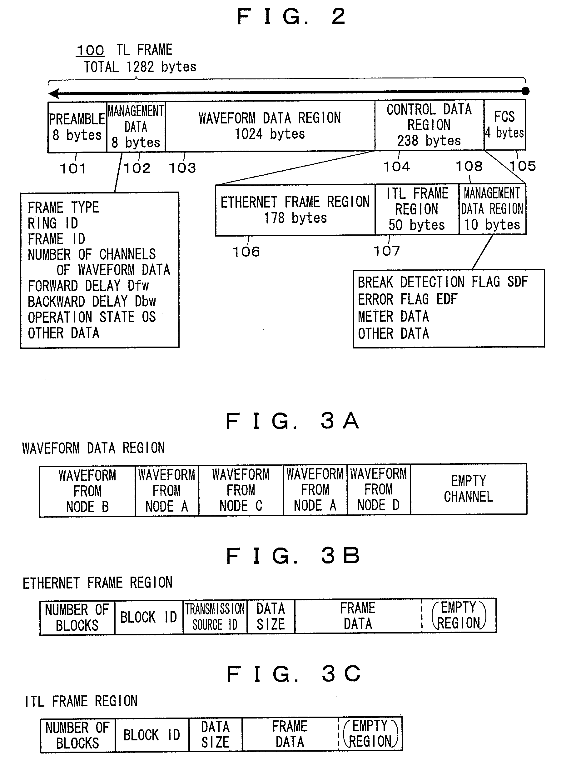
[0015]In this audio network system, waveform data is written solidly into the audio transport frame, so that the management of transportation is easy and the communication band can be efficiently utilized to perform audio transport. Since the audio transport frame circulates through all of the nodes in the system, wiring between the nodes can be easily changed regardless of the transmission route of the frame.
[0016]Further, even when an abnormality occurs in some nodes in the system, the part where the abnormality has occurred can be easily separated from the system and the remaining part of the system can keep operating.
[0020]The ring protection in SONET / SDH disclosed in Document 3 is similar to the system disclosed in Document 4 in that the communication among the nodes can be continued even if a failure occurs in the communication at a part of the nodes connected in the loop shape as described above.
[0024]The invention has been made in consideration of the above points, and its object is to make it possible for a network system in which an audio transport frame generated by a master node and including a plurality of regions for audio signals circulates along a loop transmission route formed among nodes to transport audio signals among the series of connected nodes, to shift automatically and in a short time by a simple process from / to a state in which one transmission route for the audio transport frame is formed and a frame circulates through the transmission route to / from a state in which two transmission routes for the audio transport frame are formed and frames circulate through the transmission routes respectively.
[0036]Further, in the above network systems, it is also preferable that an error check code is included in the audio transport frame which the master node generates, and each of the nodes other than the master node detects an error in the received audio transport frame based on the error check code included in the audio transport frame, and if the node detects an error in the received audio transport frame, the node prevents the audio signals read from the received audio transport frame from being outputted from the node.

Problems solved by technology

However, the conventional audio network systems described in the Documents 1 and 2 have the following problems.
Specifically, for example, in CobraNet (trademark), since a plurality of nodes transmit respectively generated frames (a plurality of frames) to a bus-type network, gaps between the frames occur, thus causing a problem of low transport efficiency.
Further, it is needed to configure the system in such a manner that data of a required number of channels can be transported in consideration of the transmission route of the frames because the physical transportation limit of number of channels varies due to change of wires between nodes (the configuration of the network), thus causing a problem of difficulties in designing the system.
This is because the time required to transmit data from a transmission source node to a node at the end varies depends on the number of nodes, and also because it takes long time to transfer data when a larger number of nodes constitute the network because the subsequent communication starts after the data is transmitted to all of the nodes, resulting in a loss of band, and so on.

Method used


Image

  • Network System and Audio Signal Processor
  • Network System and Audio Signal Processor
  • Network System and Audio Signal Processor

Examples


Embodiment Construction

[0086]Hereinafter, preferred embodiments to embody the invention will be concretely described based on the drawings.

1. Outline of Audio Network System of Embodiment of the Invention

1.1 Entire Configuration

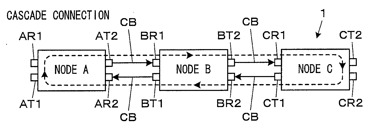
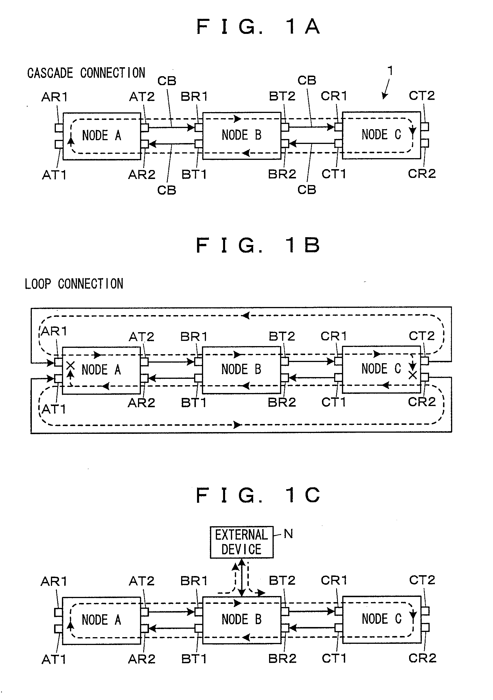
[0087]FIG. 1A to FIG. 1C show the outline of an audio network system that is an embodiment of a network system of the invention.

[0088]As shown in FIG. 1A and FIG. 1B, the audio network system 1 is constructed by connecting nodes A to C by communication cables CB in sequence, each of the nodes A to C including two sets of reception interfaces (I / Fs) being receivers and transmission I / Fs being transmitters each of which performs communication in a singe direction. Although an example composed of three nodes is shown, any number of nodes may be employed.

[0089]In the node A, a reception I / F AR1 and a transmission I / F AT1 are one set of I / Fs, and a reception I / F AR2 and a transmission I / F AT2 are another set of I / Fs. For the nodes B and C, the same relation also applies to I / Fs with a f...


PUM


Abstract

In the case of forming an audio network system in which a plurality of processors each having two sets of transmission I / Fs and reception I / Fs are connected and a TL frame generated by a master node and including a plurality of storage regions for audio signals circulates among the processors in each constant period to transport audio signals the among processors, the system is configured such that when a transmitted TL frame does not return to the reception I / F on the forward side but returns to the reception I / F on the backward side in a single mode of transmitting the TL frame to the forward side and circulating the TL frame through one transmission route, the system shifts to a twin mode of transmitting and circulating TL frames through two transmission routes.

Description

BACKGROUND OF THE INVENTION[0001]1. Field of the Invention[0002]The invention relates to a network system for transporting audio signals among a plurality of nodes and an audio signal processor capable of being incorporated into the network system as one node.[0003]2. Description of the Related Art[0004]Conventionally, an audio network system has been known for transporting audio signals between a plurality of nodes, and is used in concerts, dramas, music production, private broadcasting, and so on. Known examples of such an audio network system include CobraNet™, and EtherSound™ as described in the following Documents 1 and 2.Document 1: “CobraNet™”, [online], Balcom Co. [Retrieved on Mar. 21, 2006] Internet <URL: http: / / www.balcom.co.jp / cobranet.htm>Document 2: Carl Conrad, “EtherSound™ in a studio environment”, [online], Digigram S. A., [Retrieved on Mar. 21, 2006] Internet <URL: http: / / www.ethersound.com / news / getnews.php?enews_key=101>[0005]Known methods of transmitt...

Claims


Application Information

Patent Timeline
IPC IPC(8): H04L12/56
CPCH04L12/437H04J3/085
Inventor NAKAYAMA, KEI
Owner YAMAHA CORP
Learn More