Image processing method, image processing apparatus, and image processing program

a three-dimensional image and image processing technology, applied in the field of image processing methods, image processing apparatuses, image processing programs, etc., can solve the problems of difficult radiologists to diagnose bone regions that require careful viewing, difficult for radiologists to perform diagnosis,

Inactive Publication Date: 2010-06-17
FUJIFILM CORP
View PDF1 Cites 17 Cited by
  • Summary
  • Abstract
  • Description
  • Claims
  • Application Information

AI Technical Summary

Benefits of technology

[0050]A configuration may be adopted, wherein specified points are input within medical images which are displayed, the positions of corresponding points within pseudo three dimensional medical images that correspond to the specified points within the medical images are calculated, and markers that indicate the calculated corresponding points are displayed along with the pseudo three dimensional medical images. In this case, positions within the pseudo three dimensional medical images that correspond to the specified points within the medical images can be easily understood. Particularly, which bone within a pseudo three dimensional medical image corresponds to a bone specified by a specified point within a medical image can be easily understood.
[

Problems solved by technology

However, because the density values of bone regions represented in medical images is high, there is a tendency for the bone regions to become particularly emphasized in pseudo three dimensional medical images which are generated by the MIP method, which cause difficulties for radiologists in performing diagnosis.
Therefore, there is a problem that the bone regions cannot be diagnosed.
However, because the thoracic bones (particularly the ribs, the breastbone, and the thoracic vertebrae) are present s

Method used


Image

  • Image processing method, image processing apparatus, and image processing program
  • Image processing method, image processing apparatus, and image processing program
  • Image processing method, image processing apparatus, and image processing program

Examples


Embodiment Construction

[0062]Hereinafter, an embodiment of the present invention will be described with reference to the attached drawings.

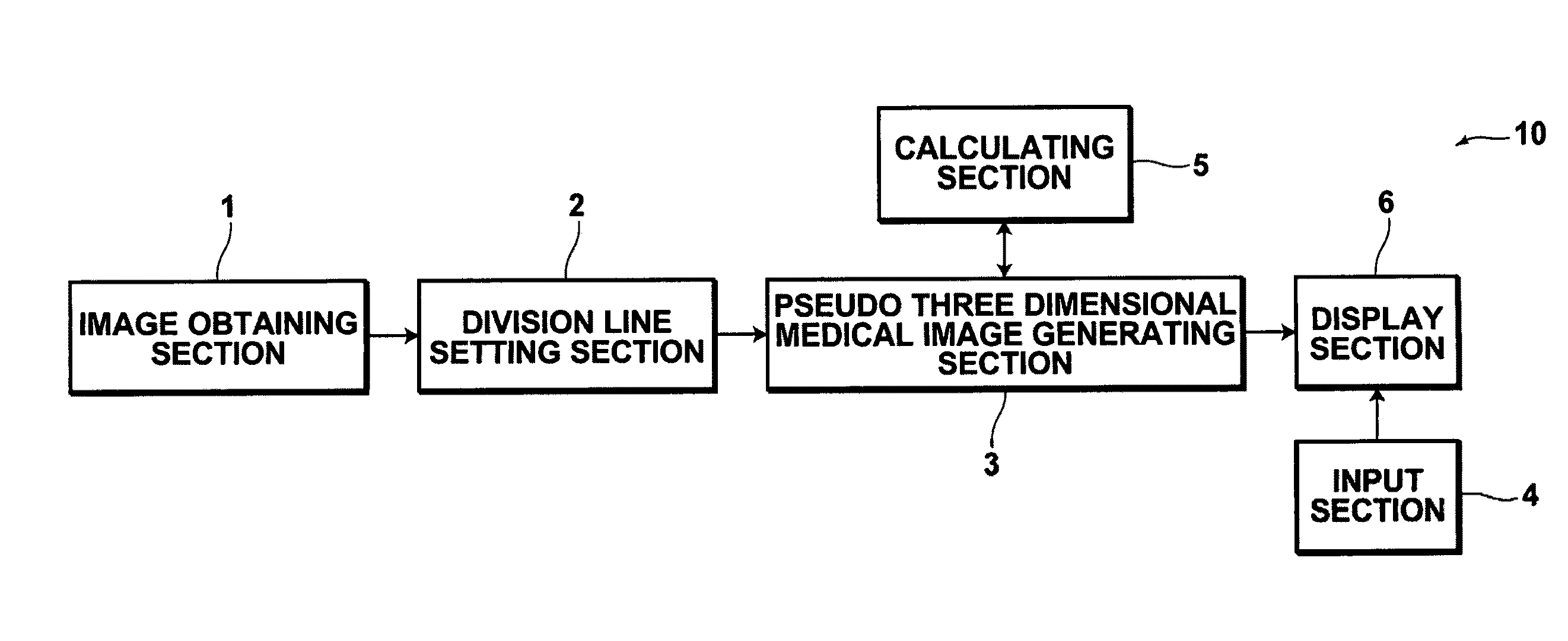
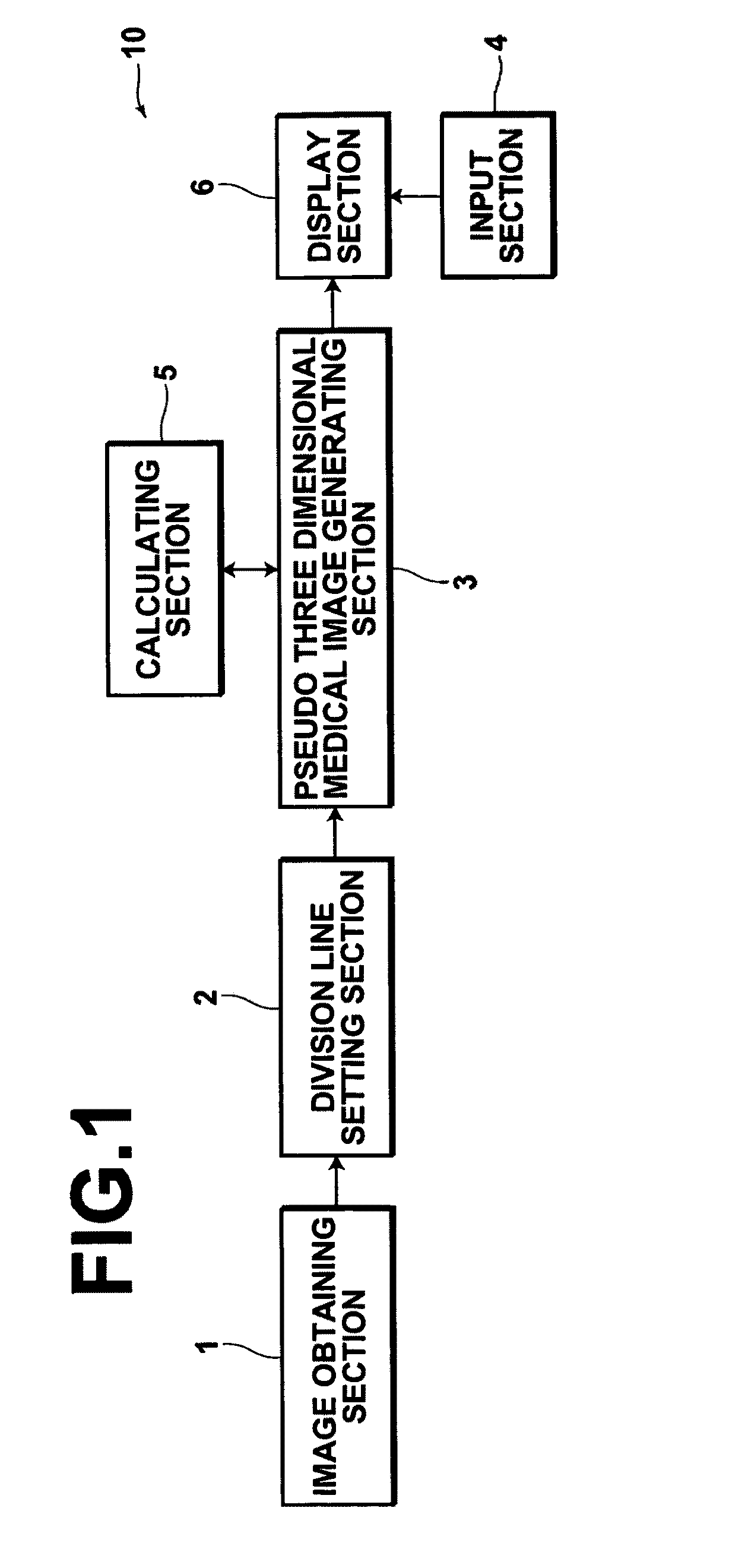
[0063]An image processing apparatus 10 illustrated in FIG. 1 is equipped with: an image obtaining section 1, for obtaining a plurality of medical images that represent transverse sections of a subject, which have been imaged in advance; a division lines setting section 2, for setting division lines within each of the plurality of medical images that divide subject regions that represent the subject in the front to back direction to display the subject regions separately, such that thoracic bones in the front to back direction of the projection direction of the subject are not displayed in an overlapping manner within pseudo three dimensional images (coronal images); a pseudo three dimensional medical image generating section 3, for generating a first pseudo three dimensional medical image by executing an intensity projection method based on a plurality of sets of image...


PUM


Abstract

An image processing apparatus includes: an image obtaining section for obtaining medical images that represent transverse cross sections of a subject, and a division line setting section, for setting division lines within each medical image that divide subject regions representing the subject front to back, such that thoracic bones in the front to back direction of the projection direction of the subject are not displayed in an overlapping manner within the pseudo three dimensional images. A pseudo three dimensional medical image generating section generates a first pseudo three dimensional medical image based image data representing subject regions toward first sides of the division lines within the medical images, and generates a second pseudo three dimensional medical image based on image data representing subject regions toward second sides of the division lines within the medical images, by executing intensity projection methods.

Description

BACKGROUND OF THE INVENTION[0001]1. Field of the Invention[0002]The present invention is related to an image processing method for generating pseudo three dimensional medical images. Particularly, the present invention is related to an image processing apparatus, an image processing method, and a computer readable medium, on which an image processing program for generating pseudo three dimensional medical images from a plurality of medical images by executing an intensity projection method is recorded.[0003]2. Description of the Related Art[0004]In the medical field, pseudo three dimensional medical images are generated by executing IP (Intensity Projection) methods that enable three dimensional medical images to be formed with respect to a plurality of medical images.[0005]The IP methods are processes by which pixels having the maximum values (alternatively, minimum values or specified values) from among corresponding pixels within all original medical images, which are the targets...

Claims


Application Information

Patent Timeline
IPC IPC(8): G06K9/62A61B5/055A61B6/03G06T1/00
CPCG06T19/00G06T2219/008G06T15/08G06T2210/41
Inventor MORIYA, YOSHIYUKIIWASAKI, TAIJI
Owner FUJIFILM CORP
Why Eureka
Try Eureka