
Brightness enhancement film and backlight module

a technology of enhancement film and backlight module, which is applied in the direction of instruments, waveguides, lighting and heating apparatus, etc., can solve the problems of reducing the accumulation of light, unable to diffuse light evenly on the display, and not having the function of accumulating light, so as to avoid moire effect and improve brightness

Inactive Publication Date: 2010-06-17
UNIVACCO TECH +1
View PDF7 Cites 7 Cited by
  • Summary
  • Abstract
  • Description
  • Claims
  • Application Information

AI Technical Summary

Benefits of technology

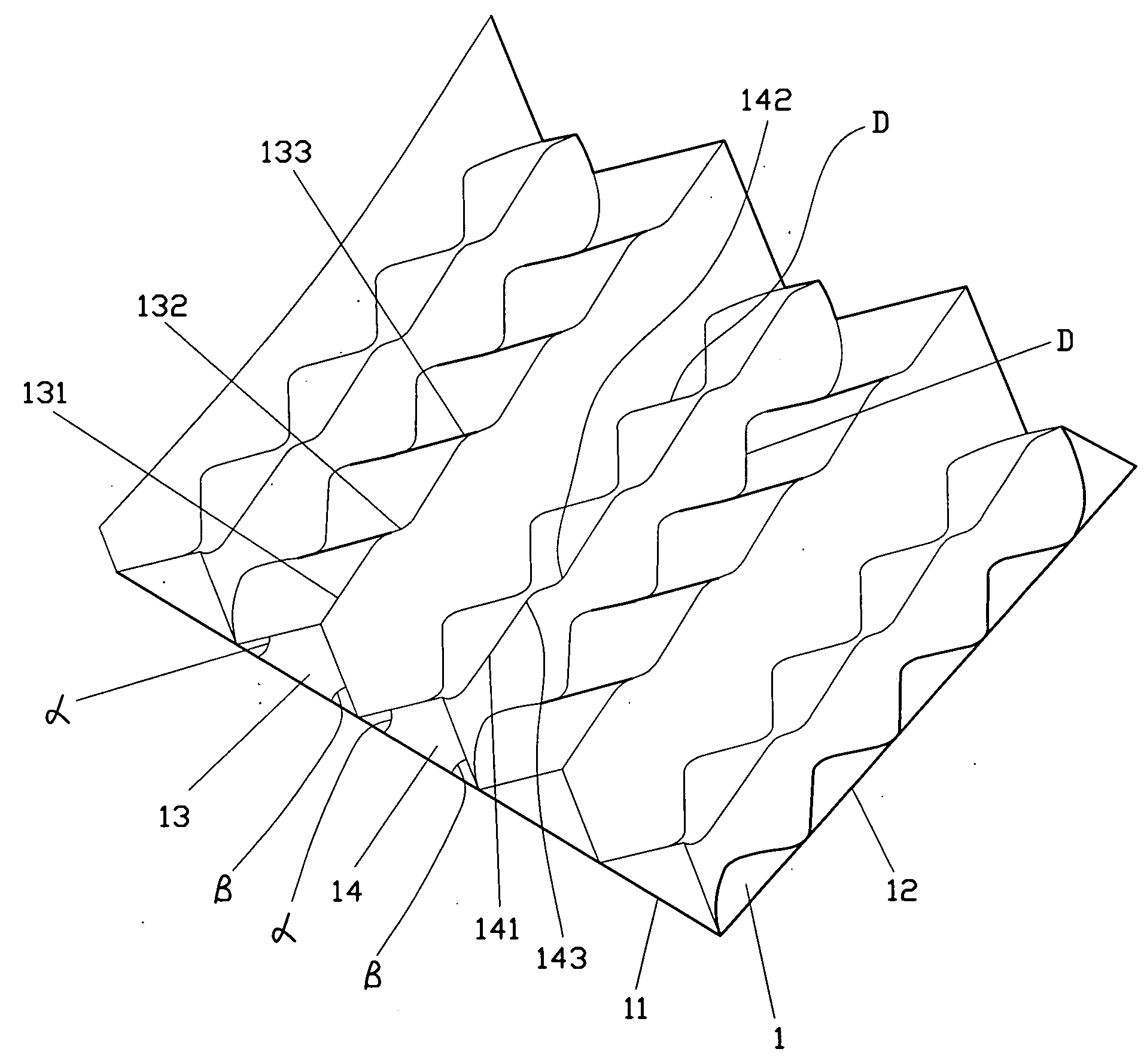
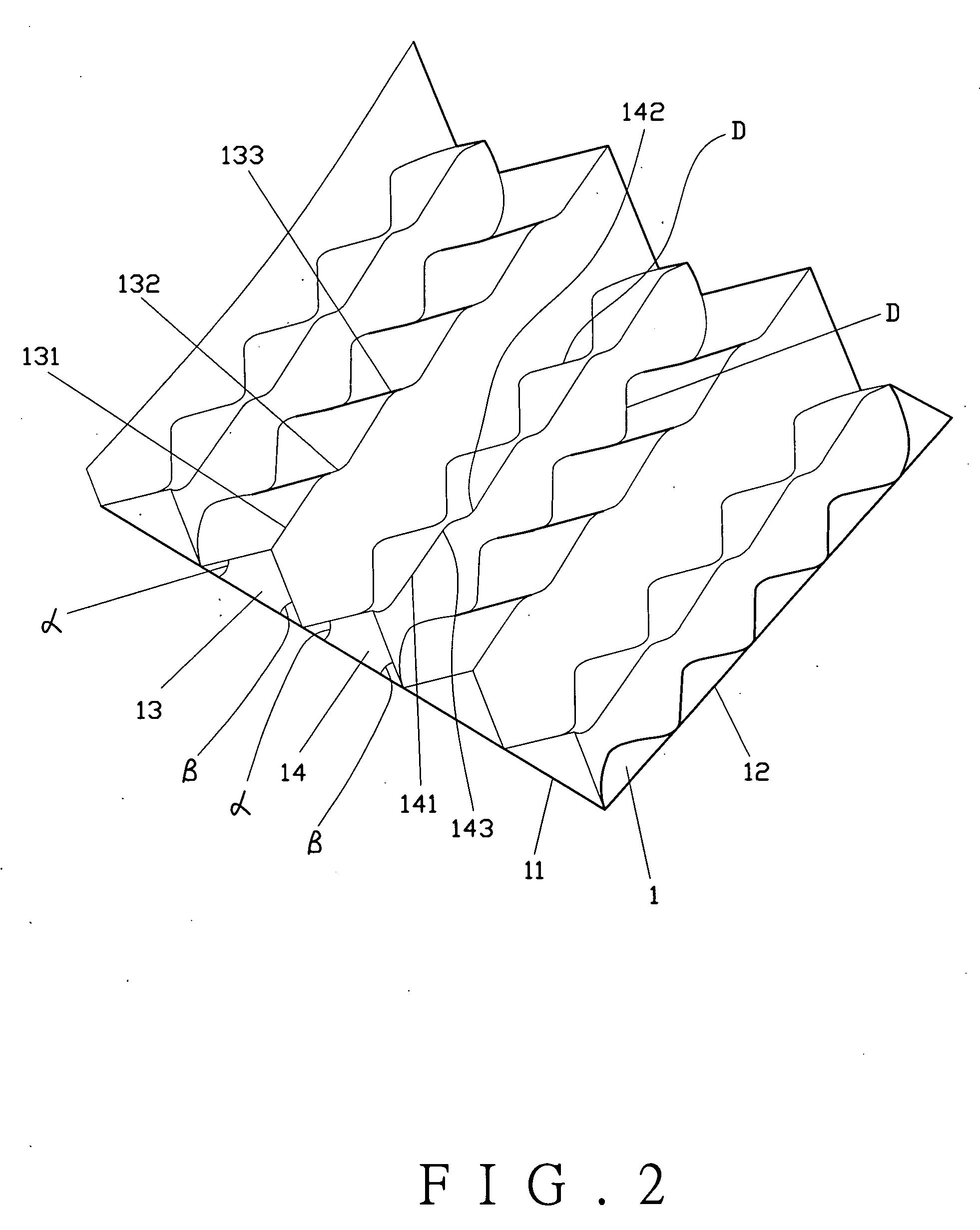
The present invention provides a brightness enhancement film that includes first and second micro-reflectors having different heights and widths. The micro-reflectors are arranged in a wavy shape, which provides better brightness and even illumination. The micro-reflectors have peaks and valleys to hold against the diffusion film, preventing distortion or damage. The valleys of the micro-reflectors also enable to collect light ray for better brightness, avoiding a moire effect. The technical effects of the invention include improved brightness and even illumination.

Problems solved by technology

However, it does not have the function of accumulating light.
However, this design can not diffuse the light evenly on the display.
However, it downgrades the accumulation of light.

Method used


Image

  • Brightness enhancement film and backlight module
  • Brightness enhancement film and backlight module
  • Brightness enhancement film and backlight module

Examples


Embodiment Construction

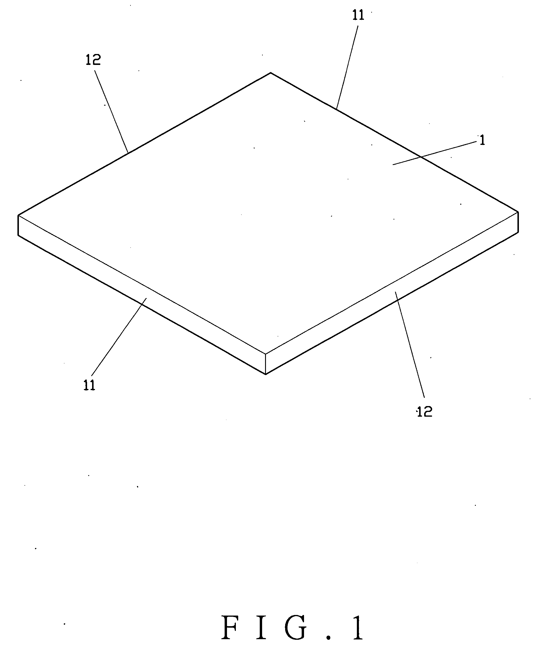
[0035]As shown in FIGS. 1 and 2, a brightness enhancement film 1 of the present invention comprises a pair of first sides 11 corresponding to each other, a pair of second sides corresponding to each other, and a number of first micro-reflectors 13 and second micro-reflectors 14 disposed side by side. Each of the first micro-reflectors 13 has a crest line 131, and each of the second micro-reflectors 14 has a crest line 141. The first micro-reflectors 13 have first average height and width which are different from second average height and width of the second micro-reflectors 14. The first average height of the first micro-reflectors 13 means the average value of the perpendicular heights of the micro-reflectors 13. The second average height of the second micro-reflectors 14 means the average value of the perpendicular heights of the second micro-reflectors 14. The first average width of the first micro-reflectors 13 means the average value of the width taken from the cross-section at...


PUM


Abstract

The present invention relates to a brightness enhancement film and a backlight module having the brightness enhancement film. The brightness enhancement film includes first micro-reflectors and second micro-reflectors. The cross-section of each of the first and second micro-reflectors is a triangle having two same or different base angles and a wavy crest line. The widths of the first and second micro-reflectors vary along with the valleys and peaks to broaden or to narrow with respect to two sides thereof such that the neighboring lines between the first and second micro-reflectors are wavy. The backlight module is coupled with the brightness enhancement film. This enhances brightness, illuminates evenly, and avoids a moire effect.

Description

BACKGROUND OF THE INVENTION[0001]1. Field of the Invention[0002]The present invention relates to a brightness enhancement film and a backlight module having the brightness enhancement film, and more particularly to a brightness enhancement film having first and second micro-reflectors in different average heights and widths and wavy crest lines. The widths of the first and second micro-reflectors vary along with valleys and peaks thereof. The neighboring lines between the first and second micro-reflectors are wavy. This enhances brightness, illuminates evenly, and avoids a moire effect.[0003]2. Description of the Prior Art[0004]A backlight module A of a conventional LCD display, as shown in FIG. 9, comprises a light guide plate A1, a light source A2, a reflector A3, a diffusion film A4, and a brightness enhancement film A5. The light source A2 is disposed at one side of the light guide plate A1 to provide light from a ray entering side A6 to the light guide plate A1 to reflect there...

Claims


Application Information

Patent Timeline
Patent Type & Authority Applications(United States)
IPC IPC(8): G02B6/10
CPCG02B6/0055G02B6/0053Y10S385/901
Inventor LIN, CHI-FENGCHEN, YI-FAN
Owner UNIVACCO TECH
Learn More