Bypass air scoop for gas turbine engine

a gas turbine engine and air scoop technology, applied in the direction of engine cooling apparatus, motors, leakage prevention, etc., can solve the problems of low pressure differential and relative high pressure loss

Active Publication Date: 2010-06-17
PRATT & WHITNEY CANADA CORP
View PDF46 Cites 51 Cited by
  • Summary
  • Abstract
  • Description
  • Claims
  • Application Information

AI Technical Summary

Problems solved by technology

The valve is usually a butterfly style and has relatively high pressure losses.
Therefore, long duct nacelle engines with a low pressure dif...

Method used


Image

  • Bypass air scoop for gas turbine engine
  • Bypass air scoop for gas turbine engine
  • Bypass air scoop for gas turbine engine

Examples


Embodiment Construction

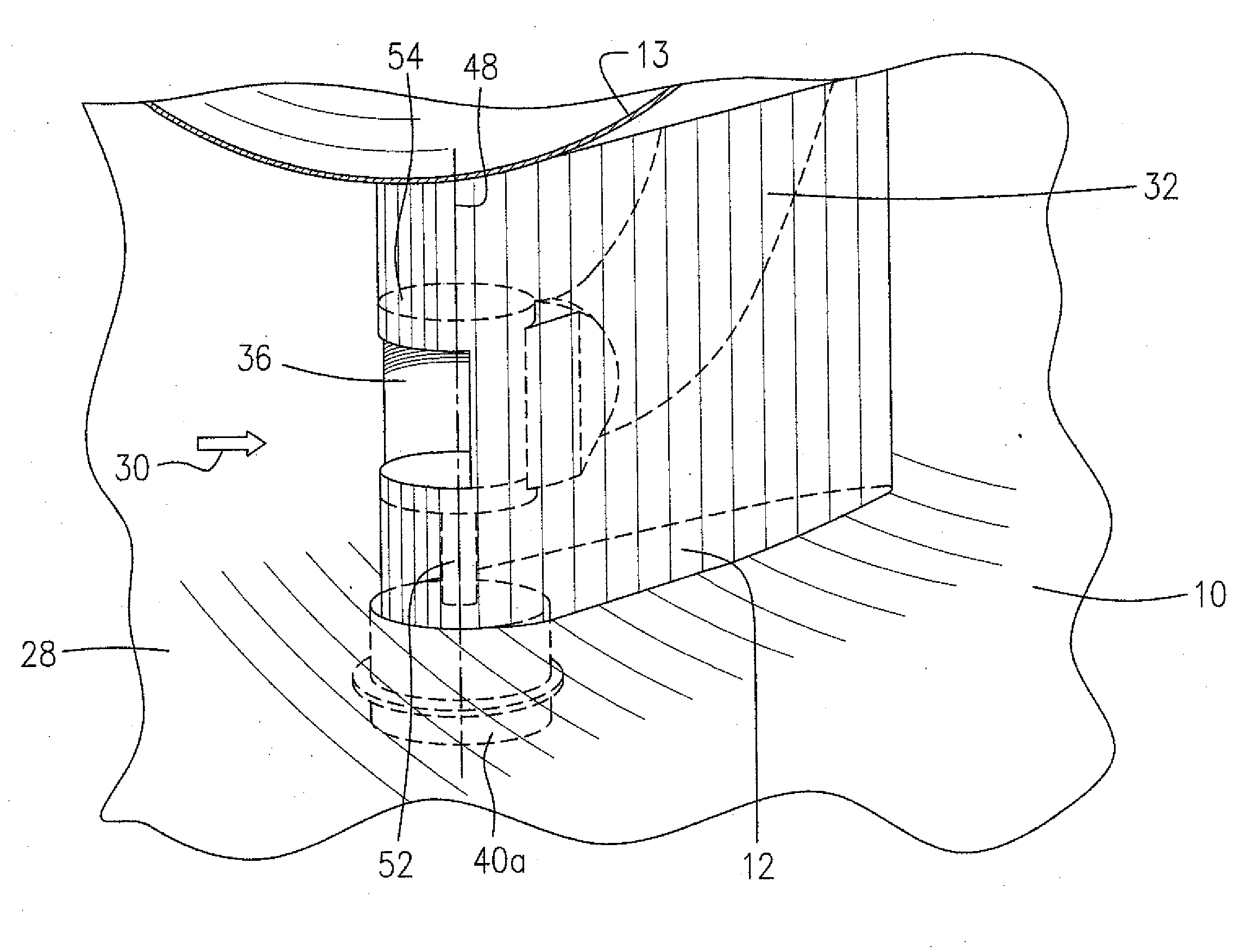
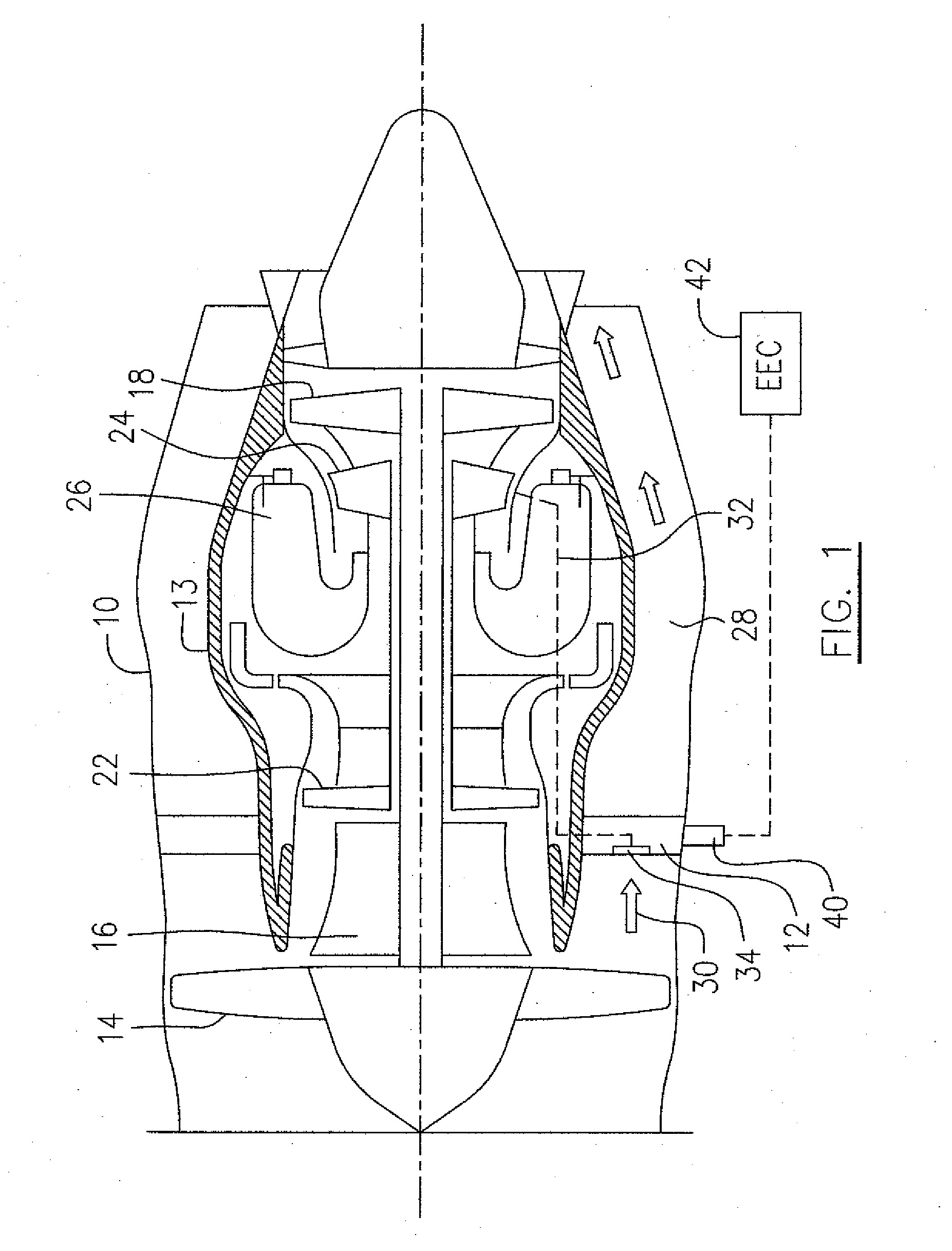
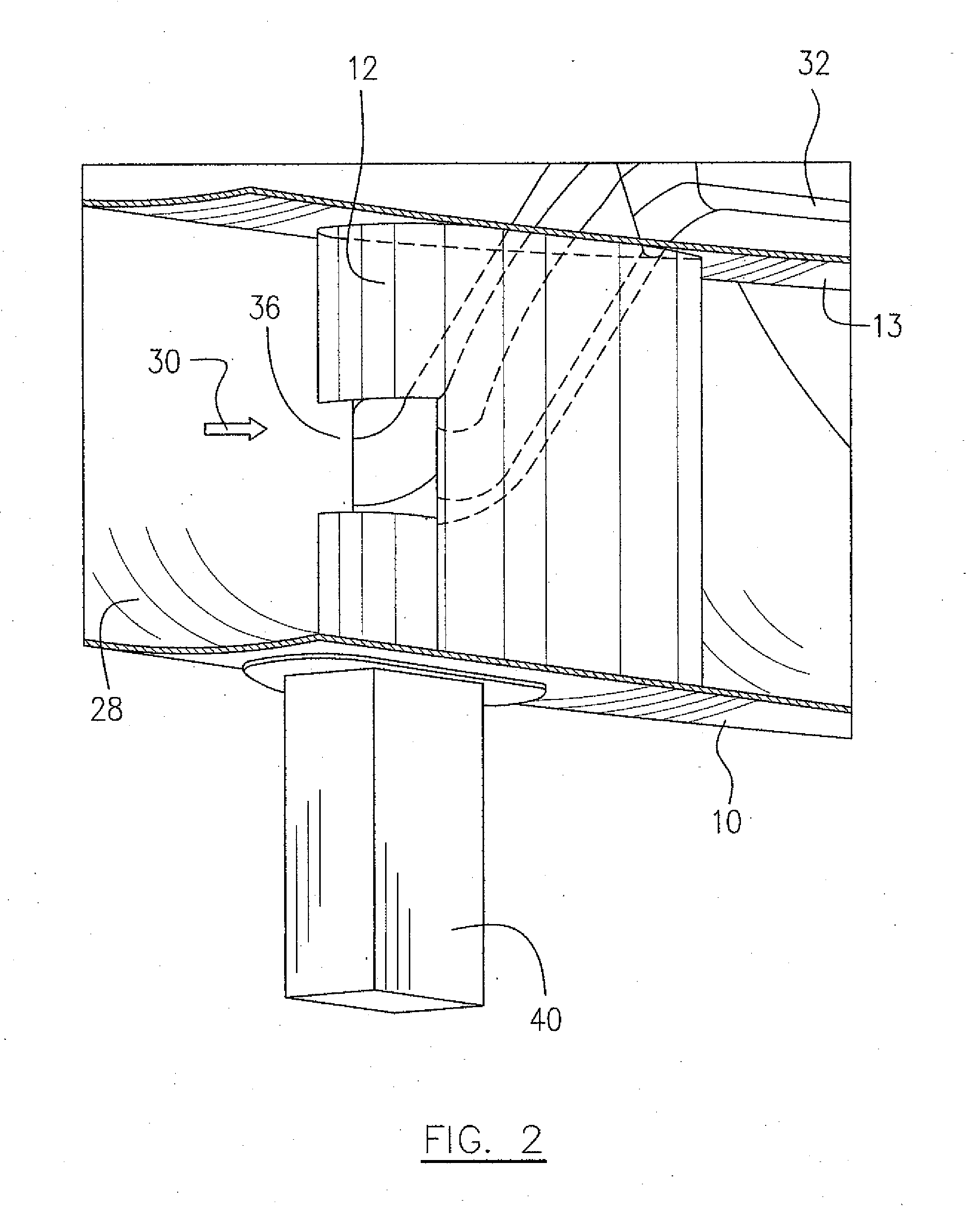
[0015]Referring to FIG. 1, a turbofan gas turbine engine includes a bypass air duct 10, a core casing 13, a low pressure spool assembly (not numbered) which includes a fan assembly 14, a low pressure compressor assembly 16 and a low pressure turbine assembly 18, and a high pressure spool assembly (not numbered) which includes a high pressure compressor assembly 22 and a high pressure turbine assembly 24. The core casing 13 surrounds the low and high pressure spool assemblies in order to define a main fluid path (not indicated) therethrough. In the main fluid path there is provided a combustion gas generator assembly 26. A plurality of struts 12 are positioned within an annular bypass air duct 28 and radially extend between the outer casing 10 and the core casing 13 which in combination define the annular bypass air duct 28. A bypass air flow (indicated by arrows 30) driven by the fan assembly 14, passes through the annular bypass air duct 28, exposing the radial struts 12 in a mid s...


PUM


Abstract

A gas turbine engine has a plurality of radial struts in a bypass duct. At least one strut has a scoop incorporated with the fairing of the strut and in communication with an air passage of an engine secondary air system. The scoop faces a bypass air flow to scoop a portion of the bypass air flow using available dynamic pressure in the bypass duct. Scooped air may be provided, for example, to an active tip clearance control apparatus in a long duct turbofan engine.

Description

TECHNICAL FIELD[0001]The application relates generally to a gas turbine engine and more particularly, to a secondary air system of a gas turbine engine which scoops bypass air flow from a bypass duct.BACKGROUND OF THE ART[0002]“Active tip clearance” refers to a gas turbine engine system whereby the radial gap between the turbine blades and surrounding static shroud is varied during the engine cycle in order to optimize tip clearance. Active tip clearance control (ATCC) usually uses compressor or bypass air to selectively cool the turbine shrouds to affect tip clearance. The use of bypass air is preferred because it is less thermodynamically “expensive” for the engine (i.e. more efficient). However, bypass air which is driven by a fan assembly is at a much lower pressure than air bled from the compressor assembly (e.g. P3 air) of the gas turbine engine. For a gas turbine engine application with a short duct nacelle, prior art utilizes a port on the side of the fan air stream bypass d...

Claims


Application Information

Patent Timeline
IPC IPC(8): F01D11/24F02C9/18F02C7/12
CPCF01D9/065F02C6/08F01D25/162F01D11/24
Inventor STRECKER, STEVENHUI, HONG-WEI
Owner PRATT & WHITNEY CANADA CORP
Why Eureka
Try Eureka