
Masking mechanism for film forming apparatus

a technology of film forming apparatus and mask, which is applied in the direction of vacuum evaporation coating, chemical vapor deposition coating, coating, etc., can solve the problems of large time expenditure, reproducible data, or no longer reliable data, and the number of masks that can be mounted

Active Publication Date: 2010-06-17
JAPAN SCI & TECH CORP
View PDF5 Cites 2 Cited by
  • Summary
  • Abstract
  • Description
  • Claims
  • Application Information

AI Technical Summary

Benefits of technology

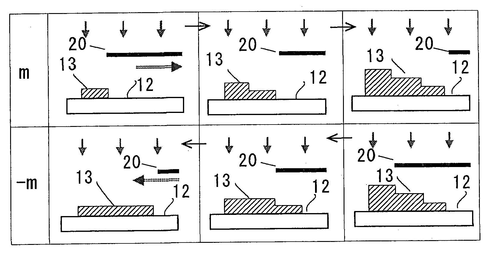
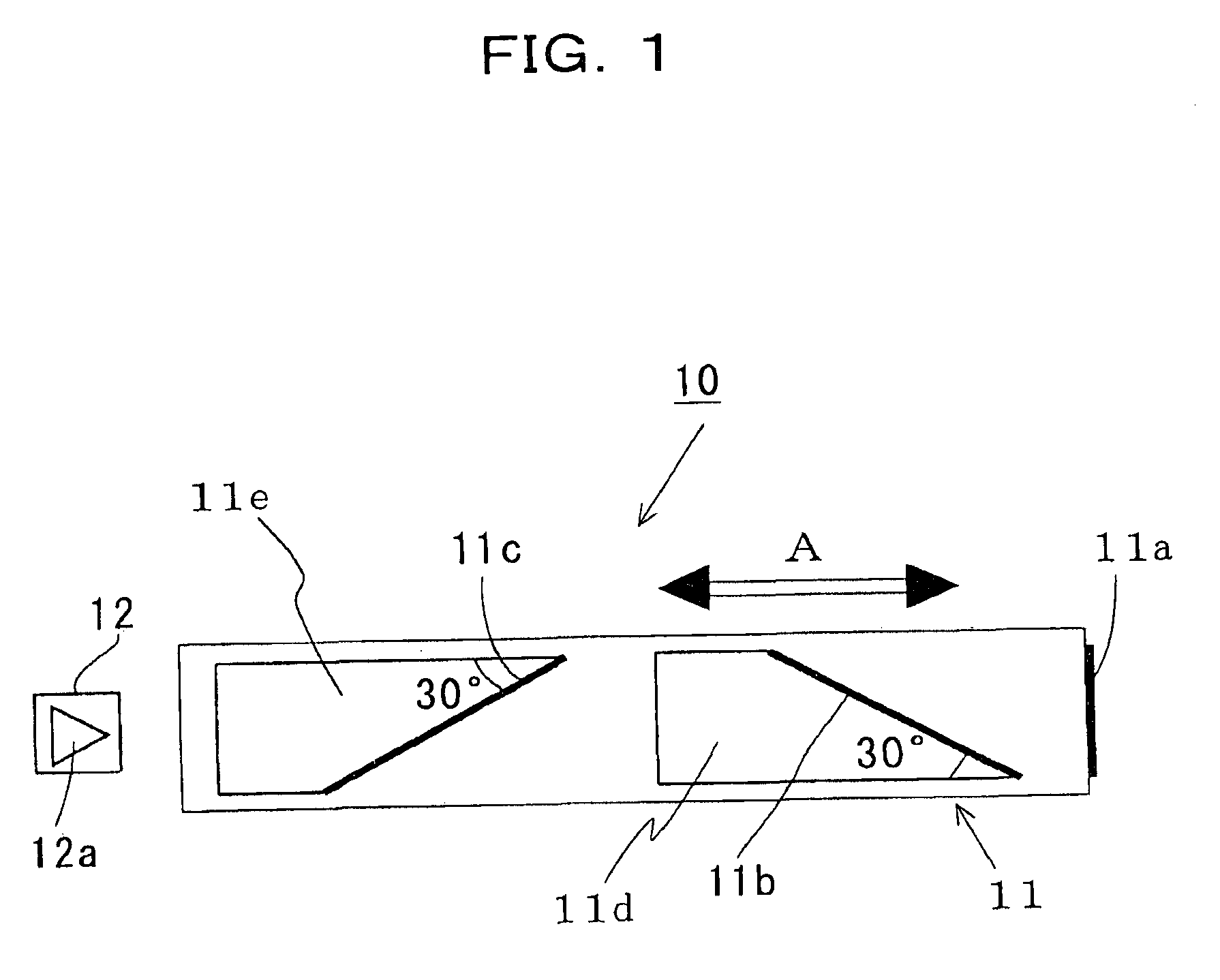
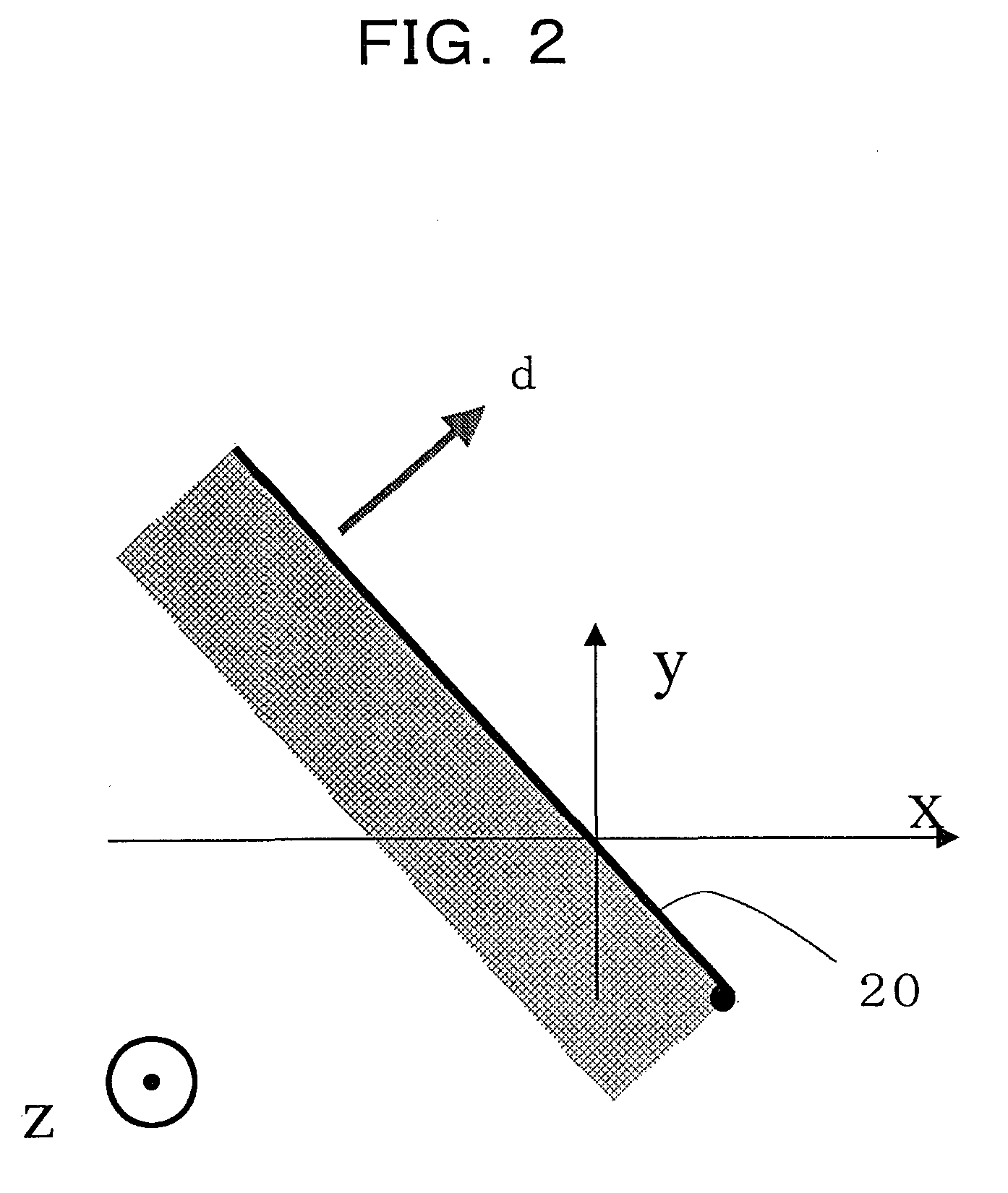
The present invention provides a masking mechanism for a film forming apparatus that can make a thin film of a ternary phase diagrammatic system without making the apparatus costly. The masking mechanism includes a single mask with a single action edge and a means for moving the mask relative to a substrate in a uniaxial direction. The mask has three edges that make an angle of 120° with each other, which allows for the formation of a thin film with a thickness gradient of the three materials. The mask is designed to produce a thin film with a high degree of accuracy and efficiency. The invention also provides a second form of the masking mechanism that includes a single mask with a first and second single action edge and a double action edge in the form of a triangle. This allows for the formation of a thin film with a high degree of accuracy and efficiency.

Problems solved by technology

In the prior method shown in FIG. 22(a), as the method requires the precise positioning among the substrate, the first mask 1 and second mask 2, however, this in turn requires spending considerable time, and in addition, as a result of which if an extremely large number of pixels are to be formed, then the film depositing conditions tend to change between the first and the last formed pixels.
Thus, for example, the substrate temperature distribution and atmospheric composition could change uncontrollably with the lapse of time, giving rise to the problem that reproducible data, or reliable data can no longer be obtained.
And, while in the prior method shown in FIG. 22(b) rotation makes it sufficient to position a given mask in less time-consuming, there the limitation in volume of the vacuum unit limits the number of masks that can be mounted and it is thus difficult to form an extremely large number of pixels with finely varied ratios of components.
It is extremely difficult, however, to include such a triaxially operating masking mechanism that must necessarily become considerably large in volume in an apparatus of this type used for material exploration, e.g., in a combinatorial film forming apparatus that makes it essential to be equipped with an ablation laser light lead-in unit, a target switching unit, a substrate heating laser unit and a reflection high-energy electron diffraction unit in a vacuum chamber.
This can be done, of course, by making the vacuum chamber in volume to an extent necessary to accommodate them, but so enlarging it requires augmenting the capacity of its vacuum pumping system correspondingly, thus making the apparatus highly costly.

Method used


Image

  • Masking mechanism for film forming apparatus
  • Masking mechanism for film forming apparatus
  • Masking mechanism for film forming apparatus

Examples


Embodiment Construction

[0052]Hereinafter, the present invention will be described in detail with reference to certain suitable forms of implementation thereof illustrated in the drawing figures.

[0053]At the outset, it should be noted that in making a thin film of a ternary phase diagrammatic system by means of a masking mechanism or device for a film forming apparatus according to the present invention, the components that make up the ternary system, as in a manner as described above in connection with the prior art for a thin film of a binary phase-diagrammatic system, are deposited successively on a common region on a substrate to form their respective thin films successively on this region while controlling the respective directions in which their thickness gradients are to develop and this laminating step is repeated several times until the deposited thin films in combination as a thin film of the ternary phase diagrammatic system have a desired thickness. In forming the composite thin film, the compo...


PUM

PropertyMeasurementUnit
angleaaaaaaaaaa
angleaaaaaaaaaa
angleaaaaaaaaaa

Abstract

It comprises a mask (11) having a first, a second and a third action edge (11a, 11b, 11c), and a drive means for moving the mask (11) relative to a substrate (12) in a uniaxial direction (A) whereby moving the mask at a fixed rate of movement to cause the edges to successively act on an identical substrate region while successively applying different materials thereto forms thin films of three components successively with respective film thickness gradients oriented in three different directions mutually angularly spaced apart by an angle of 120° to allow these films to overlap, thereby forming a ternary phase diagrammatic thin film 13.

Description

CROSS-REFERENCE TO RELATED APPLICATIONS[0001]This application is a divisional application of U.S. Ser. No. 10 / 528,265, filed Mar. 17, 2005, which is a National Phase filing of PCT / JP03 / 11950, filed Sep. 19, 2003, which is based upon and claims the benefit of priority from the prior Japanese Patent Application No. 2002-275365, filed Sep. 20, 2002, the entire contents of which are hereby incorporated by reference.TECHNICAL FIELD[0002]The present invention relates to a masking mechanism or device for a film forming apparatus for the purpose of making a thin film of compositions corresponding to a ternary phase diagram.BACKGROUND ART[0003]In recent years a number of new physical phenomena such as those of high temperature superconducting, giant magnetic resistance, high intensity fluorescence and catalysis have been discovered. Exploring a material and composition that develops such a physical phenomenon is carried out with a combinatorial film forming apparatus in order to reduce the t...

Claims


Application Information

Patent Timeline
Patent Type & Authority Applications(United States)
IPC IPC(8): B05D1/32C23C14/04
CPCC23C14/044C23C14/0015C23C14/042C23C14/56
Inventor KOINUMA, HIDEOMIYAMAMOTO, YUKIOMATSUMOTO, YUJITAKAHASHI, RYOTA
Owner JAPAN SCI & TECH CORP
Learn More