Communication system, wireless communication terminal device, position estimation device, communication relay device and connecting station

position estimation technology, applied in the field of communication systems, can solve the problems of increasing the error rate of position estimation accuracy, the inability to estimate the present position of a wireless communication terminal, and the inability to achieve position estimation, etc., to achieve simple system configuration, increase the reachability of packets, and improve the effect of accuracy

Inactive Publication Date: 2010-06-17
PANASONIC CORP
View PDF5 Cites 24 Cited by
  • Summary
  • Abstract
  • Description
  • Claims
  • Application Information

AI Technical Summary

Benefits of technology

[0237]With the arrangement as described above, for the purpose of increasing the reachability of the packet, the connecting station can transfer a plurality of the same packets. In particular, this arrangement is effective in the situation where there is high possibility that the wireless communication terminal of data transmission destination is located in the vicinity of a specific connecting station.
[0238]With the arrangement as described above, when the present invention is applied, it is possible to accomplish position estimation with high accuracy by simple system configuration using short distance communication functions. Also, according to the present invention, the position estimation with high accuracy can be achieved by utilizing bidirectionality of communication using short distance wireless devices.

Problems solved by technology

Otherwise, the position estimation cannot be accomplished.
When the wireless communication technique such as PHS is used, which can perform communication in wide area, there is a problem that error is increased in position estimation accuracy when the technique of three-point surveying is applied.
Therefore, according to the position estimation method in the prior art, it is difficult to estimate the present position of a wireless communication terminal, which cannot perform communication at current moment.
Also, when GPS is used, there is a problem in that the position cannot be specified at a place where GPS signals from GPS satellite cannot be received, e.g. in case of indoor operation.
Further, the position identified by GPS is two-dimensional coordinates such as latitude and longitude, and there is also a problem in that it is difficult to identify at which height (i.e. at which storey of a building) the wireless communication terminal is located on the same latitude and the longitude.
With the increase of the number of the IC tag reader terminals and the number of operators who carry the reader terminals, the system to be constructed must be extended to a larger scale, and this causes a problem that the cost required for the system is extensively increased.
In the prior art, when a distance from a short distance wireless device of data transmission source to the short distance wireless device of data transmission destination is very long in comparison with the communication range of each short distance wireless device, even when pairs of the short distance wireless devices are connected, a route cannot necessarily be set up from the short distance wireless device of data transmission source to the short distance wireless device of data transmission destination.
In particular, in case a distance from the short distance wireless device of data transmission source to the short distance wireless device of data transmission destination is very long, there is no communication route via the ad hoc network in some cases.
In such case, a problem may arise that data transmission cannot be carried out from the short distance wireless device of data transmission source to the short distance wireless device of data transmission destination.

Method used


Image

  • Communication system, wireless communication terminal device, position estimation device, communication relay device and connecting station
  • Communication system, wireless communication terminal device, position estimation device, communication relay device and connecting station
  • Communication system, wireless communication terminal device, position estimation device, communication relay device and connecting station

Examples


first embodiment

The First Embodiment

[0290]First, description will be given on a first embodiment of the invention. In the first embodiment of the invention, description will be given on a case where the device ID to be stored is associated with time information.

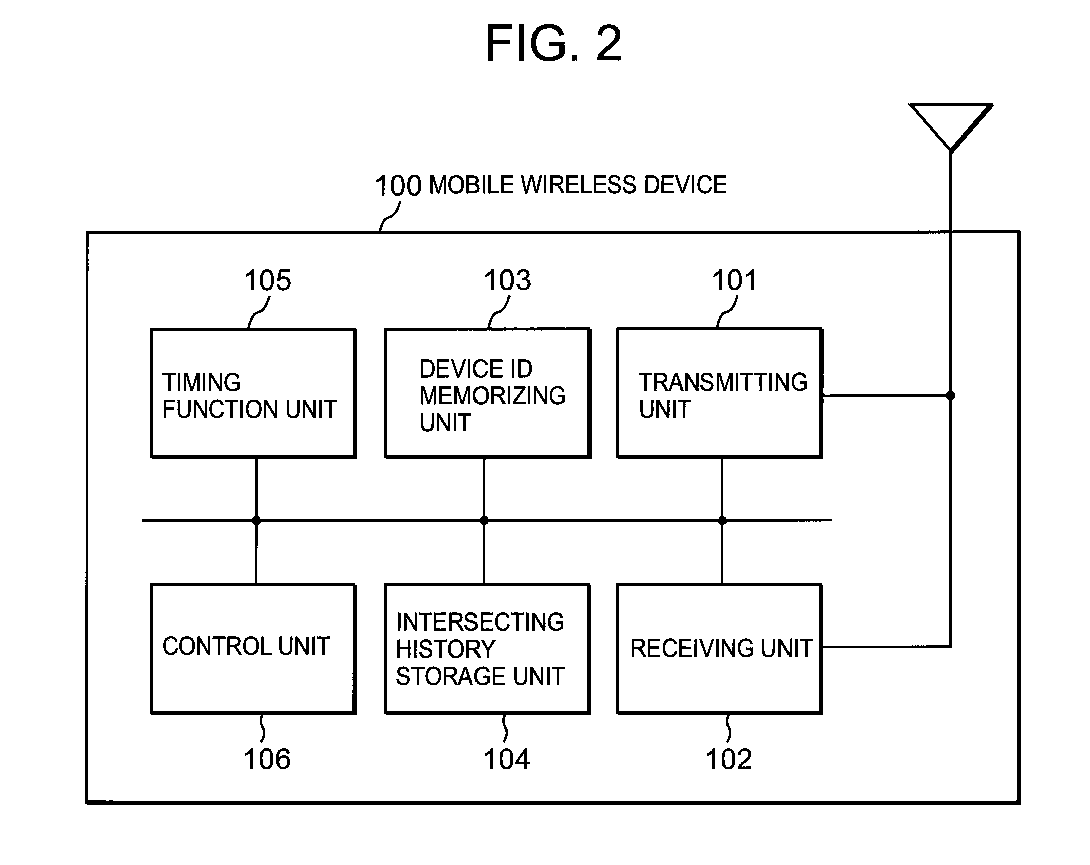
[0291]FIG. 2 is a block diagram to show an example of an arrangement of the mobile wireless device 100 in the first embodiment of the invention. The mobile wireless device 100 as shown in FIG. 2 comprises a transmitting unit 101, a receiving unit 102, a device ID memorizing unit 103, an intersecting history storage unit 104, a timing function unit 105, and a control unit 106. FIG. 2 shows a condition where these functional blocks are connected with each other via an internal bus.

[0292]The transmitting unit 101 and the receiving unit 102 have the functions to perform wireless communication with other wireless devices (i.e. other mobile wireless devices 100, standard stations 110, and the connecting stations 120). According to the present inve...

second embodiment

The Second Embodiment

[0344]Next, description will be given on the second embodiment of the invention. In the second embodiment, description will be given on a case where a device ID to be kept in memory is associated with information on the number of strides (or moving distance information).

[0345]FIG. 9 shows an example of an arrangement of a mobile wireless device 100 in the second embodiment of the invention. The mobile wireless device 100 as shown in FIG. 9 comprises a transmitting unit 101, a receiving unit 102, a device ID memorizing unit 103, an intersecting history storage unit, a timing function unit 105, a control unit 106, an a stride number counting unit 905. FIG. 9 schematically shows a condition where these functional blocks are connected via internal bus.

[0346]As it is evident from the comparison with the arrangement shown in FIG. 2, the mobile wireless device 100 in the second embodiment of the invention has such an arrangement that a stride number counting unit 905 i...

third embodiment

The Third Embodiment

[0370]First, description will be given on the third embodiment. In the third embodiment of the invention, description will be given on a case where a mobile wireless device 110 identifies its own position according to the time required when it has moved from a standard station 1110, of which the position is already known.

[0371]FIG. 12 shows an example of an arrangement of a mobile wireless device 1100 in the third embodiment of the invention. The mobile wireless device 1100 as shown in FIG. 12 comprises a transmitting unit 1101, a receiving unit 1102, a device ID memorizing unit 1103, an intersecting history storage unit 1104, a timing function unit 1105, a standard position information acquiring unit 1106, a position estimation processing unit 1107, and a control unit 1108. FIG. 12 shows a condition where these functional blocks are connected via internal bus.

[0372]The transmitting unit 1101 and the receiving unit 1102 have the functions to perform wireless comm...


PUM


Abstract

The present invention discloses a technique, according to which estimation of a position of a mobile wireless device can be accomplished in a simple system configuration by using short distance communication functions. A plurality of standard stations 110 and a plurality of connecting stations 120 are installed within a predetermined area. A mobile wireless device moving within the predetermined area has short distance wireless communication functions and receives a device ID of an opponent device (a correspondent device) each time it intersects another mobile wireless device or a standard station, and stores the device ID as an intersecting history data. When the mobile wireless device moves to a position where it can perform communication to and from a connecting station, which can make access to a position estimation device 150, the stored intersecting history data is uploaded to the position estimation device. The intersecting history data as uploaded from the mobile wireless device is stored in an intersecting history database 155. The position estimation device identifies positions of installation of all standard stations, and it estimates a moving route of the mobile communication device (for which the position is to be estimated) according to the intersecting history data directly uploaded from the mobile wireless device (for which the position is to be estimated) and a moving route of the mobile wireless device (for which the position is to be estimated) is estimated according to the intersecting history with the mobile wireless device (for which the position is to be estimated) as included in the intersecting history data of another mobile wireless device.

Description

TECHNICAL FIELD[0001]The present invention relates to a communication system, a wireless communication terminal, and a position estimation device for estimating a position of a wireless communication terminal (a mobile wireless device) having functions to perform wireless communication. The invention also relates to a communication system, a wireless communication terminal, a communication relay device, and connecting stations having functions to perform wireless communication. In particular, the invention relates to a communication system, a wireless communication terminal, and a position estimation device for estimating a position of a short distance wireless device having functions to perform short distance wireless communication, and the invention also relates to a communication system, a wireless communication terminal, a communication relay device, and connecting stations, which form an ad hoc network where a short distance wireless device having functions for short distance w...

Claims


Application Information

Patent Timeline
Patent Type & Authority Applications(United States)
IPC IPC(8): H04B7/00G01S5/02H04W60/00
CPCG01S5/0036H04W60/00G01S5/0252G01S5/02521
Inventor SUZUKI, YOSHIHIROKAWAKAMI, TETSUYA
Owner PANASONIC CORP
Why Eureka
Try Eureka