Intraocular Lens and Method of Making an Intraocular Lens

Inactive Publication Date: 2010-06-17
BAUSCH & LOMB INC
View PDF23 Cites 9 Cited by
  • Summary
  • Abstract
  • Description
  • Claims
  • Application Information

AI Technical Summary

Benefits of technology

[0005]In a first aspect, the present invention addresses, in one or more embodiments thereof, the first need by providing an IOL having an optic with a peripheral section including one or more visually observable inversion markers formed on the optic peripheral section and located within the visually observable zone of a surgeon viewing the IOL in the implanted condition through the pupil.
[0006]In a second aspect, the present invention addresses, in one or more embodiments thereof, the second need by providing an IOL having a plunger engagement segment formed on the optic peripheral edge. The plunger engagement segment is configured to inhibit

Problems solved by technology

For some IOL designs, and in particular IOL designs bilaterally symmetrically disposed about an axis extending perpendicularly through the lens' optical axis, it may be difficult to visually ascertain which surface is the anterior surface and which is the posterior surface.
As such, it is difficult, if not impossible, for a surgeon to confirm whether or not the IOL 10 has been implanted with the anterior surface the

Method used


Image

  • Intraocular Lens and Method of Making an Intraocular Lens
  • Intraocular Lens and Method of Making an Intraocular Lens
  • Intraocular Lens and Method of Making an Intraocular Lens

Examples


Embodiment Construction

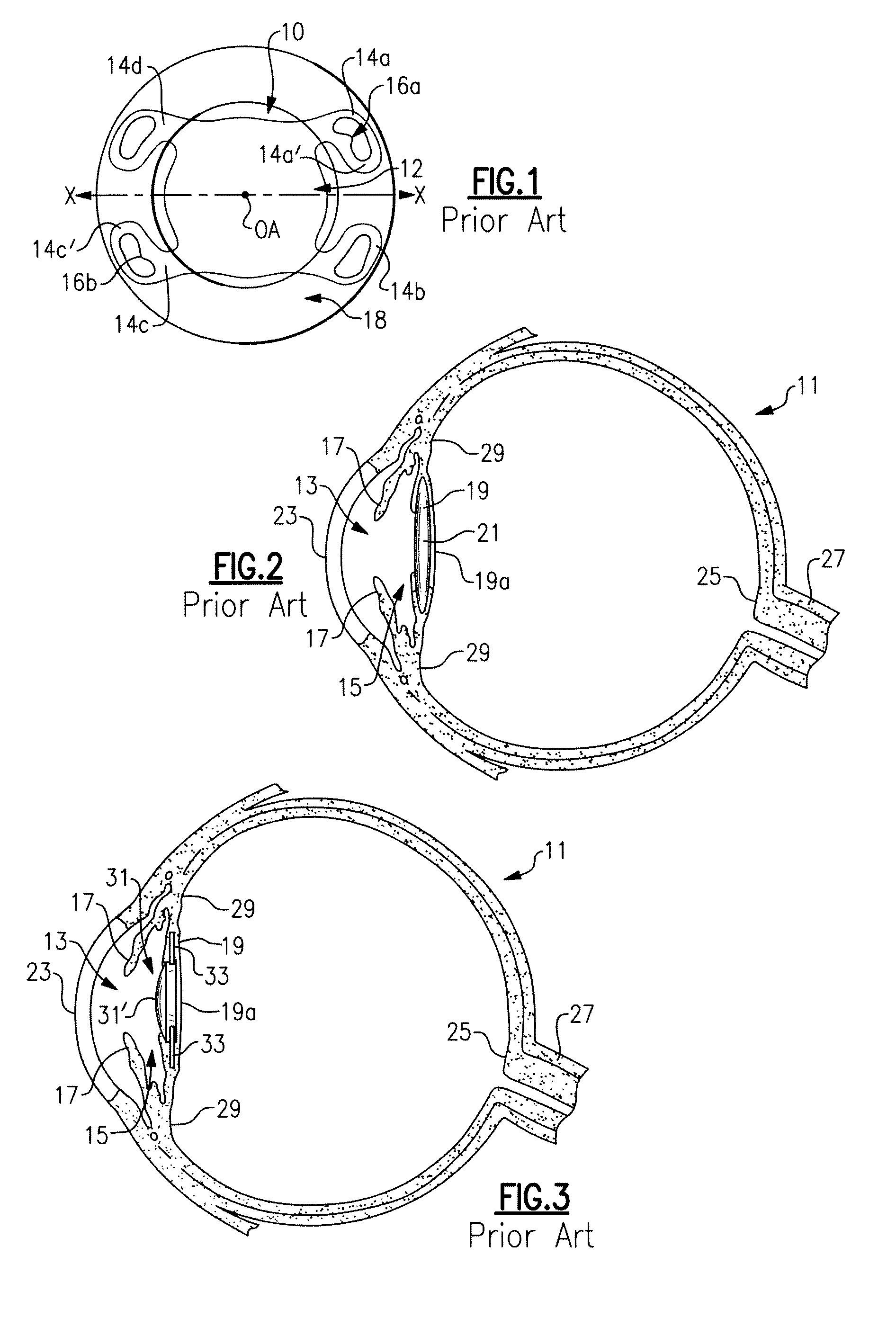
[0020]Referring now to the drawing, there is seen in FIG. 2 a cross-sectional view of a human eye 11 having an anterior chamber 13 and a posterior chamber 15 separated by the iris 17. Within the posterior chamber 15 is a capsule 19 which holds the eye's natural crystalline lens 21. Light enters the eye by passing through the cornea 23 to the crystalline lens 21 which act together to direct and focus the light upon the retina 25 located at the back of the eye. The retina connects to the optic nerve 27 which transmits the image received by the retina to the brain for interpretation of the image.

[0021]In an eye where the natural crystalline lens has been damaged (e.g., clouded by cataracts), the natural lens is no longer able to properly focus and direct incoming light to the retina and images become blurred. A well known surgical technique to remedy this situation involves removal of the damaged crystalline lens which may be replaced with an artificial lens known as an intraocular len...


PUM


Abstract

In a first aspect, the invention provides an IOL having an optic with a peripheral section including one or more visually observable markers formed on the optic peripheral section and located within the visually observable zone of a surgeon viewing the IOL in the implanted condition through the pupil. In a second aspect of the invention, the IOL peripheral section includes an edge provided with a plunger engagement segment configured to inhibit off-axis movement of a plunger tip when engaged therewith.

Description

BACKGROUND OF THE INVENTION[0001]The present invention relates to intraocular lenses. In a first aspect, the invention more particularly relates to an intraocular lens (“IOL”) having a visually observable inversion marker formed on a peripheral section of the optic. The visually observable inversion marker may be seen through an appropriate ophthalmic viewing instrument such as a slit lamp or a binocular microscope during surgery, for example, to aid a surgeon or other practitioner in confirming proper orientation of the IOL within a patient's eye. In a second aspect, the invention provides an IOL having a plunger engagement segment formed on the optic peripheral edge. The plunger engagement segment is configured to inhibit off-axis movement of the IOL relative to a plunger tip when engaged therewith and advanced to inject the IOL into an eye.[0002]IOLs are well known and are used for implanting into an eye to replace the eye's extracted natural lens in a common surgical procedure k...

Claims


Application Information

Patent Timeline
IPC IPC(8): A61F2/16
CPCA61F2/1613A61F2250/0097A61F2/1662
Inventor VAILLANT, YANNBESSIERE, BENOIT
Owner BAUSCH & LOMB INC
Why Eureka
Try Eureka