
Method and device for optimizing the flight of an aircraft

a flight optimization and aircraft technology, applied in the field of aircraft flight management systems, can solve the problems of difficult grasping of the relationship between the cost index ci and the speed, significant drawbacks, pilots being forced to change speed, etc., and achieves the effect of facilitating strategic flight optimization, fast obtaining the main predictions, and facilitating understanding

Inactive Publication Date: 2010-06-17
THALES SA
View PDF19 Cites 26 Cited by
  • Summary
  • Abstract
  • Description
  • Claims
  • Application Information

AI Technical Summary

Benefits of technology

[0035]Another advantage of the invention is that of facilitating the understanding of the use of the cost index CI over its non-linear span of values. The invention therefore facilitates the strategic flight optimization managed by the flight management system through the modification of the cost index CI and the fast obtainment of the main predictions for the remainder of the flight. The invention allows vice versa the calculation and the consideration of a CI on the basis of the speed entered.
[0036]The invention also facilitates the tracking over a given period (for example several months) of the cost index CI over a given route on the basis of the initial cost index CI adjusted by the pilot according to the vagaries encountered. This makes it possible to propose the use of a cost index CI that is more suited to the route and to the conditions of the day, which may then be considered in a systematic manner by the operator. This involves a strategic means of adapting the cost index CI, helping to improve cost-effectiveness in a simple and precise manner depending on daily vagaries (delay on departure, headwinds, lengthening / shortening of the route, etc.), starting from a base cost index CI recommended by the operator. The scheme based on cost index CI is nowadays the finest means for optimizing a flight. The choice of a cruising regime (Long Range, Min Time, Maxi range) is merely a flight optimization trend that does not replace the benefit of using the cost index CI for which applications are developed that aid operators to optimize the flight according to the routes of their network.
[0037]The invention will be better understood and other advantages will become apparent on reading the detailed description given by way of nonlimiting example and with the aid of the figures among which:

Problems solved by technology

The relationship between the cost index CI and the speed is not easy for the pilot to grasp.
A problem arises in particular when the pilot is obliged to change speed because of an order from air traffic control, for example.
This represents a considerable drawback, notably at high altitudes, when the aeroplane flies under a regime close to the maximum engine regime.
Moreover, the pilot of the aircraft is completely ignorant of the impact on the flight time, the difference in consumption and the Mach / speed discrepancy.
The use of a secondary flight plan to fine-tune a new cost index is hardly practical.
This makes it essential to use the same flight plan as the active flight plan not allowing calculation and direct display of the discrepancies in remaining flight time, and speed and consumption discrepancies.
Moreover, this manipulation monopolizes a secondary flight plan, which is no longer available for other activities.

Method used


Image

  • Method and device for optimizing the flight of an aircraft
  • Method and device for optimizing the flight of an aircraft
  • Method and device for optimizing the flight of an aircraft

Examples


Embodiment Construction

[0043]An aircraft speed setpoint in terms of indicated speed (Indicated / Calibrated Air Speed) or in terms of Mach onwards of a certain altitude, is formulated as a function of the following parameters: the weight of the aircraft, the scheduled cruising altitude, a cost index CI and meteorological parameters (wind, temperature).

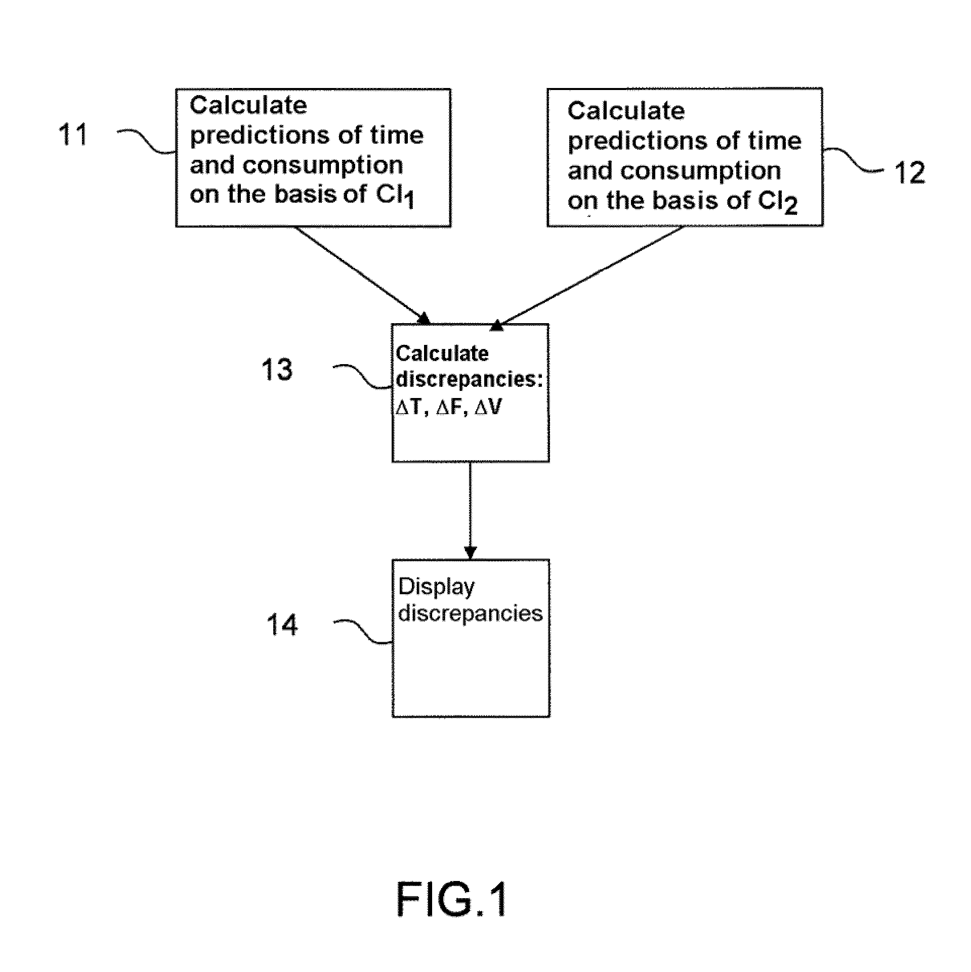
[0044]On the basis of the weight of the aeroplane, of the cruising altitude and of the meteorological parameters, the method according to the invention calculates, for each cost index CI proposed by the pilot, a setpoint speed and discrepancies of fuel consumption, remaining flight time, and speed.

[0045]FIG. 1 represents a flowchart illustrating the main steps of the method according to the invention. This method is implemented in an aircraft comprising a flight management system. This flight management system uses a first cost index CI1 and calculates a first speed setpoint V1 on the basis of the first cost index CI1. This flight management system calculates ...


PUM


Abstract

The invention relates to a method for optimizing the flight of an aircraft comprising a flight management system, the said flight management system using a first cost index (CI1) and calculating a first speed setpoint (V1) on the basis of the first cost index (CI1), the said flight management system calculating (11), furthermore, a first prediction of remaining flight time (T1) and a first prediction of fuel consumption (EFOB1) on the basis of the first speed, the said method being characterized in that it comprises, furthermore, the following steps:the selection of a second cost index (CI2),the calculation (12) by the flight management system of a second speed setpoint (V2) on the basis of the second cost index (CI2), of a second prediction of remaining flight time (T2) and of a second prediction of consumption (EFOB2) on the basis of the second speed (V2),the calculation (13) of a discrepancy (ΔV) between the first and the second speed, of a discrepancy (ΔT) between the first prediction of remaining flight time and the second prediction of remaining flight time and of a discrepancy (ΔEFOB) between the first and the second prediction of consumption,the displaying (14) of the discrepancies (ΔV,ΔT,ΔEFOB) calculated in the previous step.The invention allows vice versa the calculation and the consideration of a CI on the basis of the speed entered.

Description

TECHNICAL FIELD[0001]The present invention relates to aircraft flight management systems, designated by the acronym FMS (“Flight Management System”), and more particularly to a flight optimization method formulated by such systems.BACKGROUND OF THE INVENTION[0002]These FMS flight management systems are well known. They make it possible to formulate the flight plan of an aircraft on each mission, by taking account of parameters specific to the aeroplane and to the flight conditions such as the payload, the weight of the aeroplane, the quantity of fuel on board, the temperature, the wind etc., and of the time constraints imposed by the ATC air traffic control bodies: departure and / or arrival time slot required.[0003]Guidance to the flight plan is performed by considering target speeds for each phase of the flight: climb, cruising and descent. These speeds depend on the objective fixed by the company and achieve a compromise between flight time and fuel consumption. According to its ob...

Claims


Application Information

Patent Timeline
IPC IPC(8): G01C23/00G06F19/00G06F3/048
CPCG05D1/0005
Inventor SACLE, JEROMECAMBON, PHILLIPE
Owner THALES SA
Learn More