

Sensing method, accuracy control method, workpiece positioning system and workpiece positioning method
a technology of workpiece positioning and positioning system, applied in the field of sensing method, can solve the problems of complex operation of robots, deviations outside the allowable range after final welding, and inability to position components, etc., and achieve the effect of convenient positioning a plurality of workpieces
- Summary
- Abstract
- Description
- Claims
- Application Information
AI Technical Summary
Benefits of technology
Problems solved by technology
Method used
Image

Examples
first exemplary embodiment
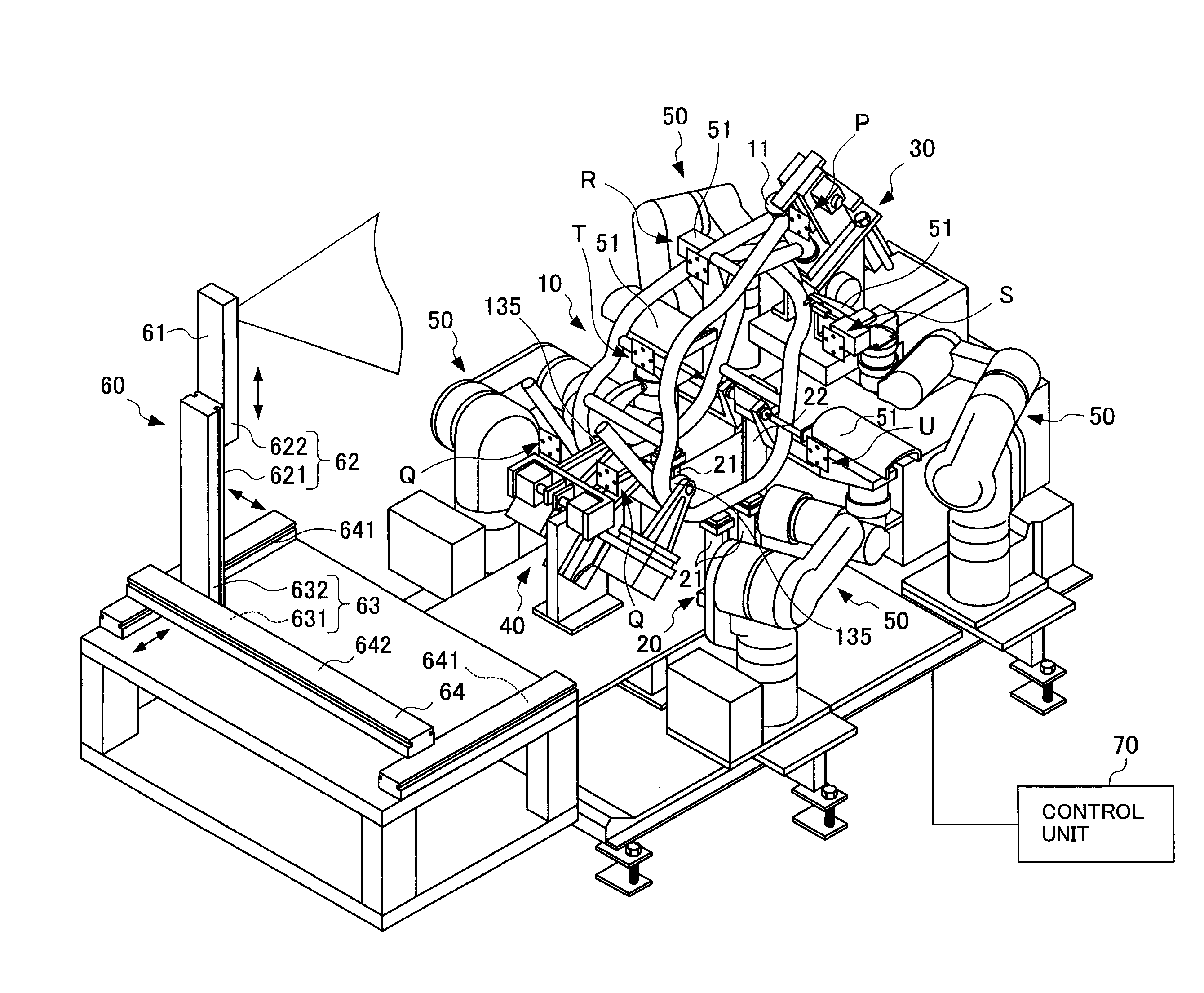
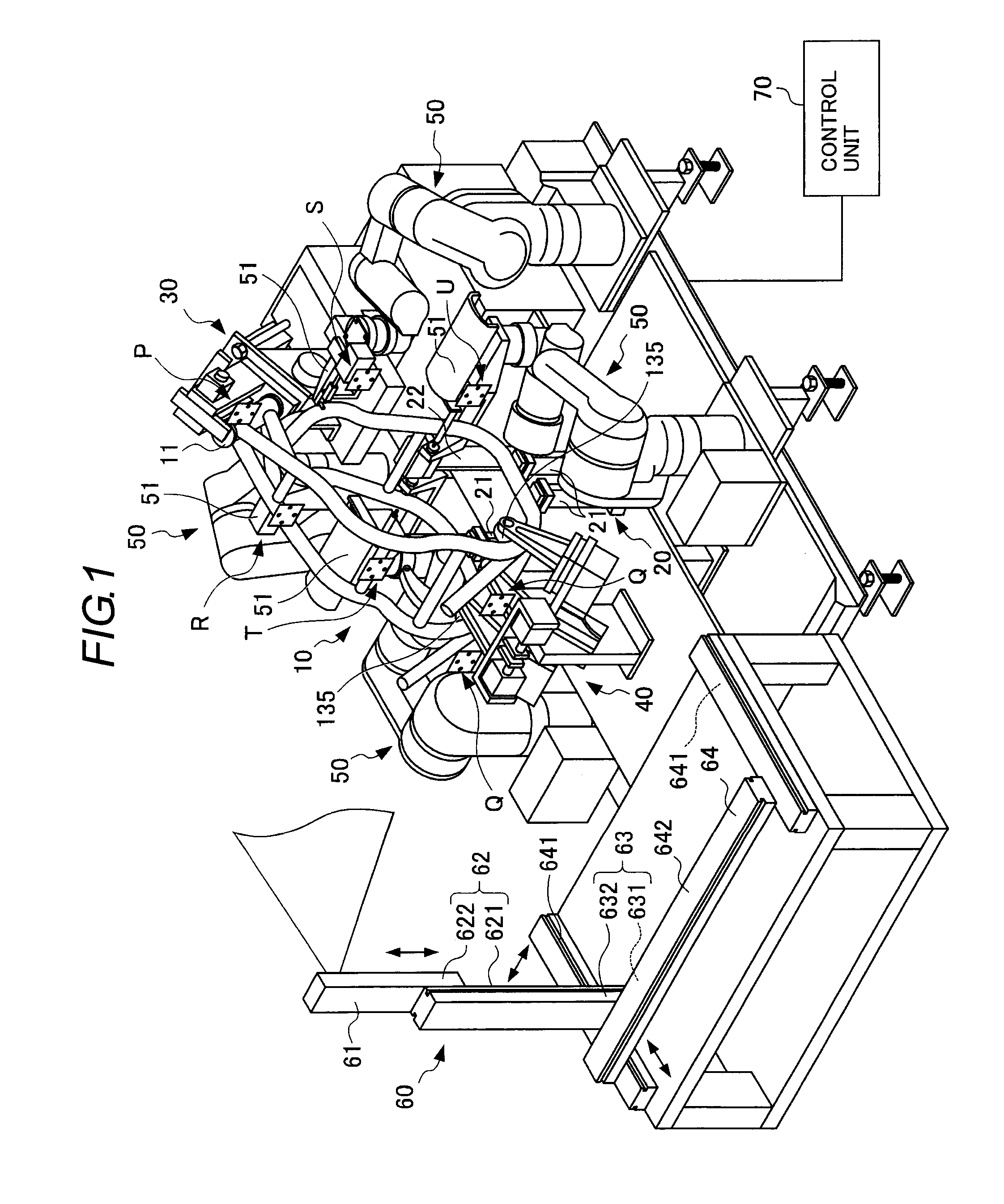
[0046]FIG. 1 is a perspective view illustrating a measuring system 1 to which a sensing method according to a first exemplary embodiment of the present invention is applied. The measuring system 1 measures, when a frame 10 is welded, the accuracy of welding performed on this frame 10. This measuring system 1 includes: a support device 20 for supporting the frame 10; a first gripping robot 30 located at the front of this support device 20; a second gripping robot 40 located at the rear of the support device 20; four third gripping robots 50 located to surround the support device 20; and a measuring device 60 functioning as a sensing device located behind the second gripping robot 40.
[0047]Further, these first gripping robot 30, second gripping robot 40, four third gripping robots 50 and measuring device 60 are controlled by a control unit 70.
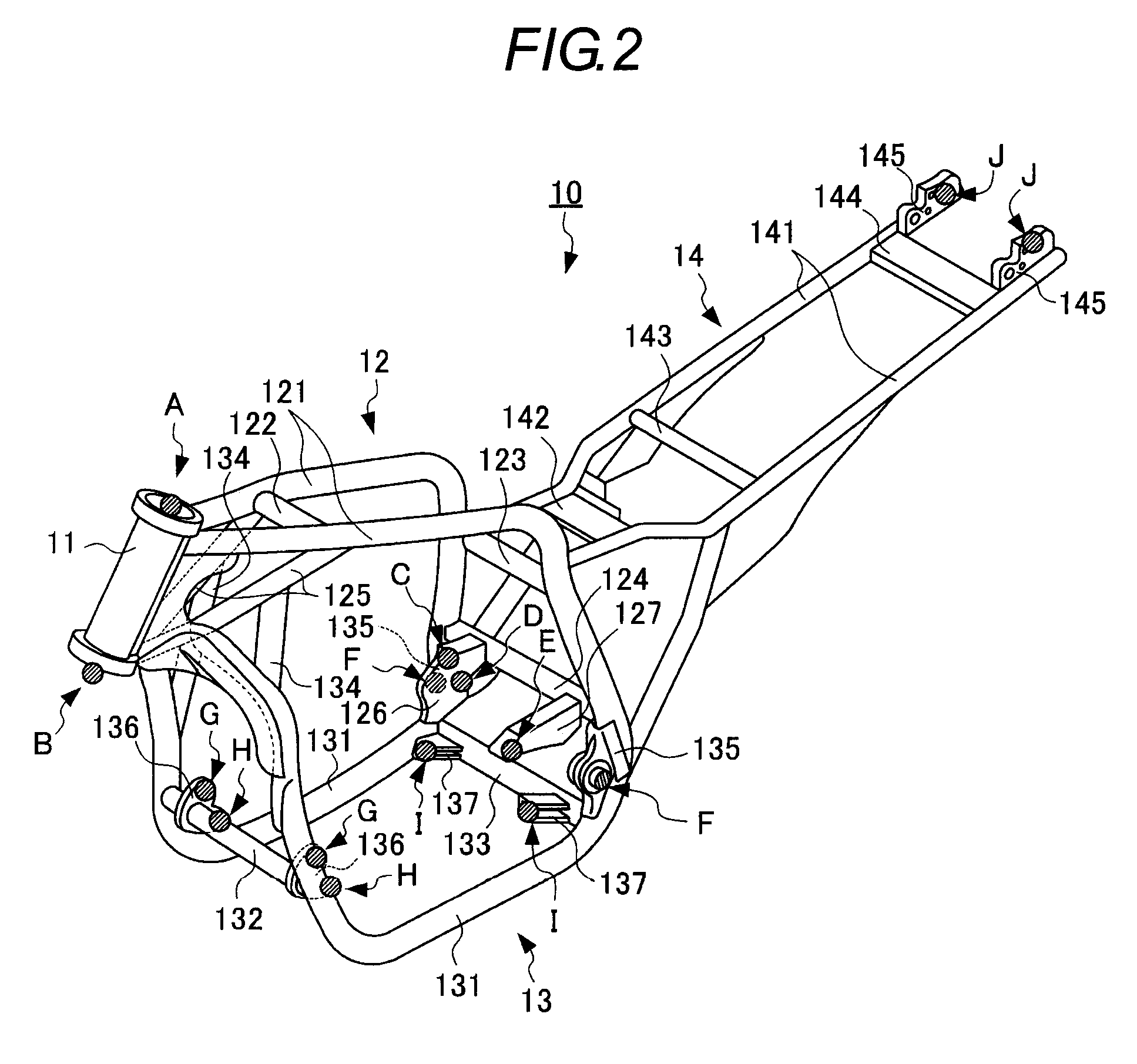
[0048]FIG. 2 is a perspective view of the frame 10. The frame 10 is a frame of a motorcycle, and includes the following four components: a head ...
second exemplary embodiment
[0068]FIG. 3 is a perspective view of a frame 80. The structure of the frame 80 according to a second exemplary embodiment is different from that of the frame according to the first exemplary embodiment. The frame 80 includes: a head tube 81; an engine upper part 82; an engine lower part 83; and a rear part 84.
[0069]The head tube 81 is formed into a cylindrical shape, and its upper side portion is inclined rearward. This head tube 81 is provided, at its upper and lower ends, with measurement points A and B, respectively.
[0070]The engine upper part 82 includes: an engine upper frame 821 extending approximately horizontally rearward from the head tube 81; a pair of branching frames 822 branching off from a tip of this engine upper frame 821 and extending downward therefrom; and a sub-frame 823 extending forward from the tip of the engine upper frame 821.
[0071]Each of the pair of branching frames 822 is provided with a measurement point C. Lateral faces of the sub-frame 823 are each pr...
third exemplary embodiment
[0078]A third exemplary embodiment of the invention will be described with reference to FIGS. 6 to 8. FIG. 6 is a perspective view illustrating a frame examination system 1001 to which an accuracy control method according to the third exemplary embodiment of the present invention is applied. The frame examination system 1001 controls the accuracy of welding when a frame 1010 is finally welded. This frame examination system 1001 includes: a support device 1020 for supporting the frame 1010; a measuring device 1030 located laterally of the frame 1010; and a control unit 1040 for controlling this measuring device 1030.
[0079]FIG. 7 is a perspective view of the frame 1010. The frame 1010 is a frame of a motorcycle, and includes the following four components: a head tube 1011; an engine upper part 1012; an engine lower part 1013; and a rear part 1014.
[0080]The head tube 1011 supports a front fork including a front wheel and a steering wheel. This head tube 1011 is formed into a cylindrica...
PUM
| Property | Measurement | Unit |
|---|---|---|
| Area | aaaaa | aaaaa |
Abstract
Description
Claims
Application Information