Liquid applying apparatus

Inactive Publication Date: 2010-06-24
CANON KK
View PDF56 Cites 4 Cited by
  • Summary
  • Abstract
  • Description
  • Claims
  • Application Information

AI Technical Summary

Benefits of technology

[0010]An object of the present invention is to solve the above problems and is to provide a liquid applying apparatus which includes a simple liqui

Problems solved by technology

When a pair of electrodes in contact with the liquid in a tube is used as the liquid sensor, there arises the problem that quick detection is difficult especially in the returning operation depending on the state of the viscosity or the like of the liquid according to a change of the environmental conditions.
As a result of this, when the operations of filling and returning of the liquid are performed in a continued flow of a printing operation, the print operation may become slow as a whole.
However, when an installation place is small like the inside of a tube, if electrodes are disposed to be greatly apart from each other, the resistance value of a liquid becomes large.
Therefore, the dynamic range of the conduction

Method used


Image

  • Liquid applying apparatus
  • Liquid applying apparatus
  • Liquid applying apparatus

Examples


first embodiment

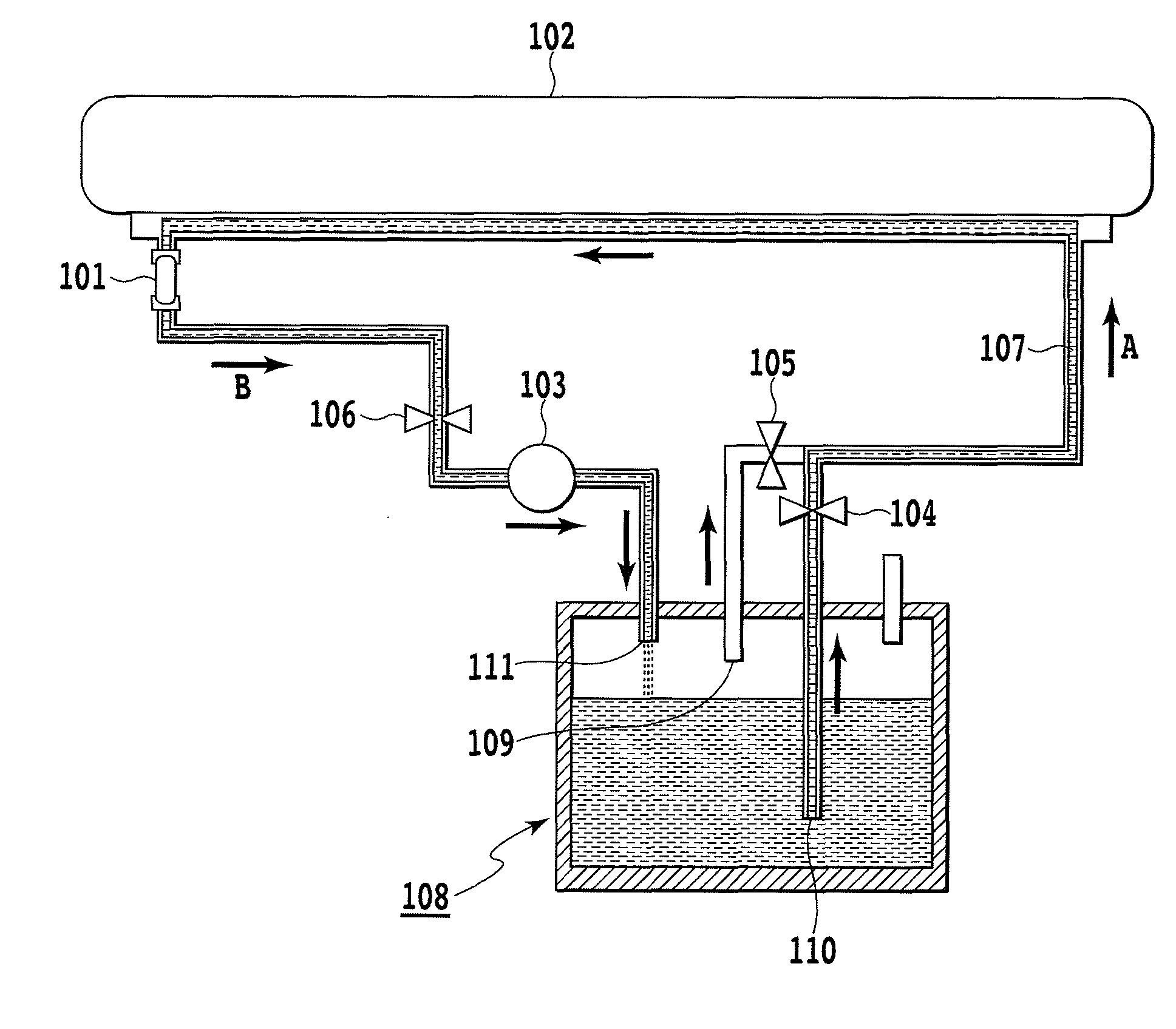
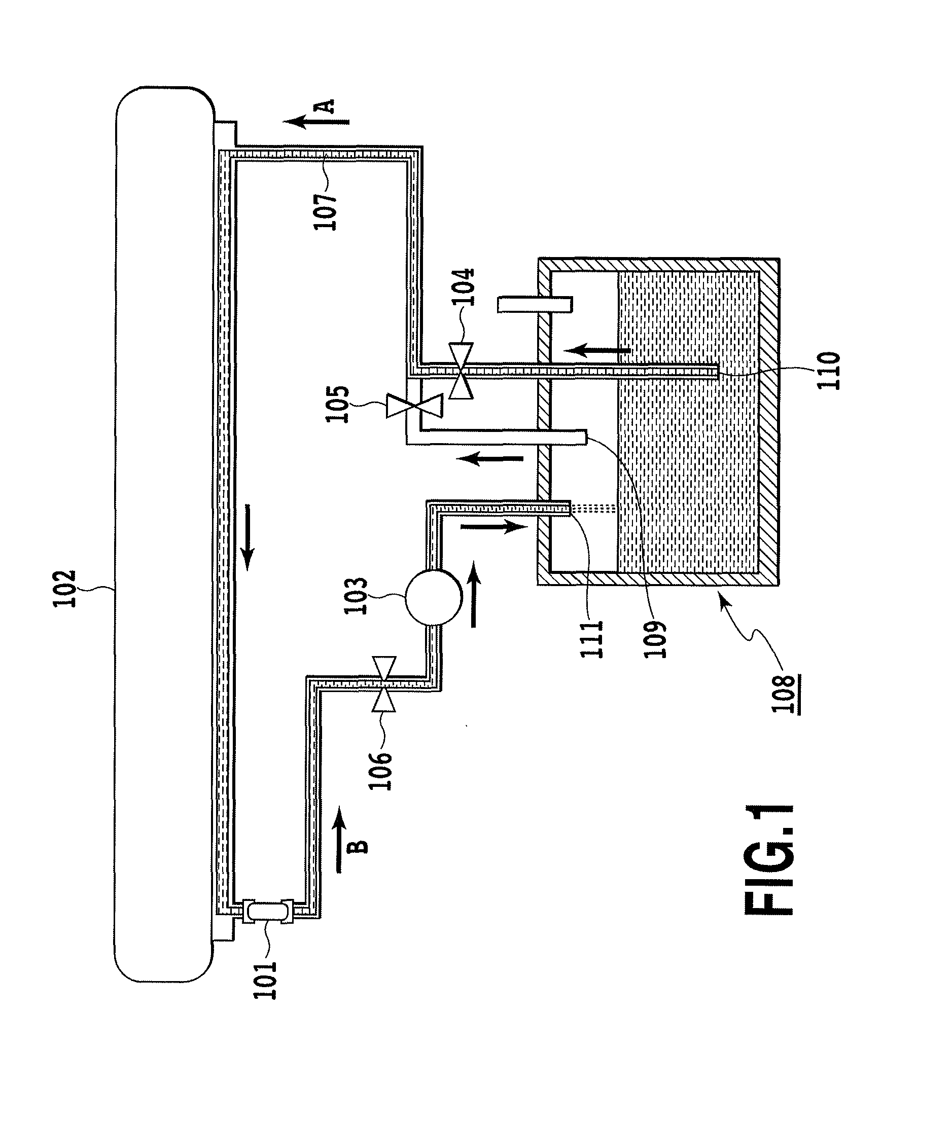
[0033]FIG. 1 is a schematic view showing a main part of a liquid applying apparatus according to a first embodiment of the present invention. In FIG. 1, a liquid retained in a tank 108 is supplied in a direction of the arrow A in the drawing through a tube 107 to fill a liquid holding portion of a liquid applying mechanism 102 with the liquid. Further, at a non-operating time of the liquid applying apparatus, the liquid is discharged in a direction of the arrow B in the drawing from the above described liquid holding portion and is returned to the tank 108. The operations of supply and filling, and discharge and returning of the liquid are performed by driving a pump 103. The liquid applying mechanism 102 includes the liquid holding portion and an applying roller as described later with reference to FIGS. 14 to 15, so that the liquid held in the liquid holding portion contacts with the applying roller, and thereby, the liquid is supplied onto the applying roller. The supplied liquid...

second embodiment

[0051]A second embodiment of the present invention differs in the calculating method of the threshold value Th1 from the aforementioned first embodiment, and the other structure and operation are the same as those of the first embodiment.

[0052]In the calculating method of the returning threshold value Th1 in the second embodiment, the returning threshold value Th1 is calculated by the following calculation formula by using the voltage value Vh acquired at the time of the filling operation which is performed immediately before the returning operation.

Th1=α×1 / Vh

[0053]Here, α is a constant. The returning threshold value Th1 is calculated by performing the arithmetic operation of inverse proportion for Vh. FIG. 12 is a diagram showing the relationship of Th1 and Vh in the case of α=12.

third embodiment

[0054]A third embodiment of the present invention likewise differs in the calculating method of the returning threshold Th1 from the first embodiment, and the other structure and operation are the same as those of the first embodiment.

[0055]In the calculating method of the returning threshold value Th1 of the third embodiment, the returning threshold value Th1 is calculated by the following calculation formula by using the voltage value Vh which is acquired at the time of the filling operation which is performed immediately before the returning operation.

Th1=α×1 / Vh+β

[0056]Here, α and β are constants. The returning threshold value Th1 is calculated by performing the arithmetic operation of proportion for Vh. FIG. 13 is a diagram showing the relationship of Th1 and Vh in the case of α=−0.6 and β=5.40.

Other Embodiments

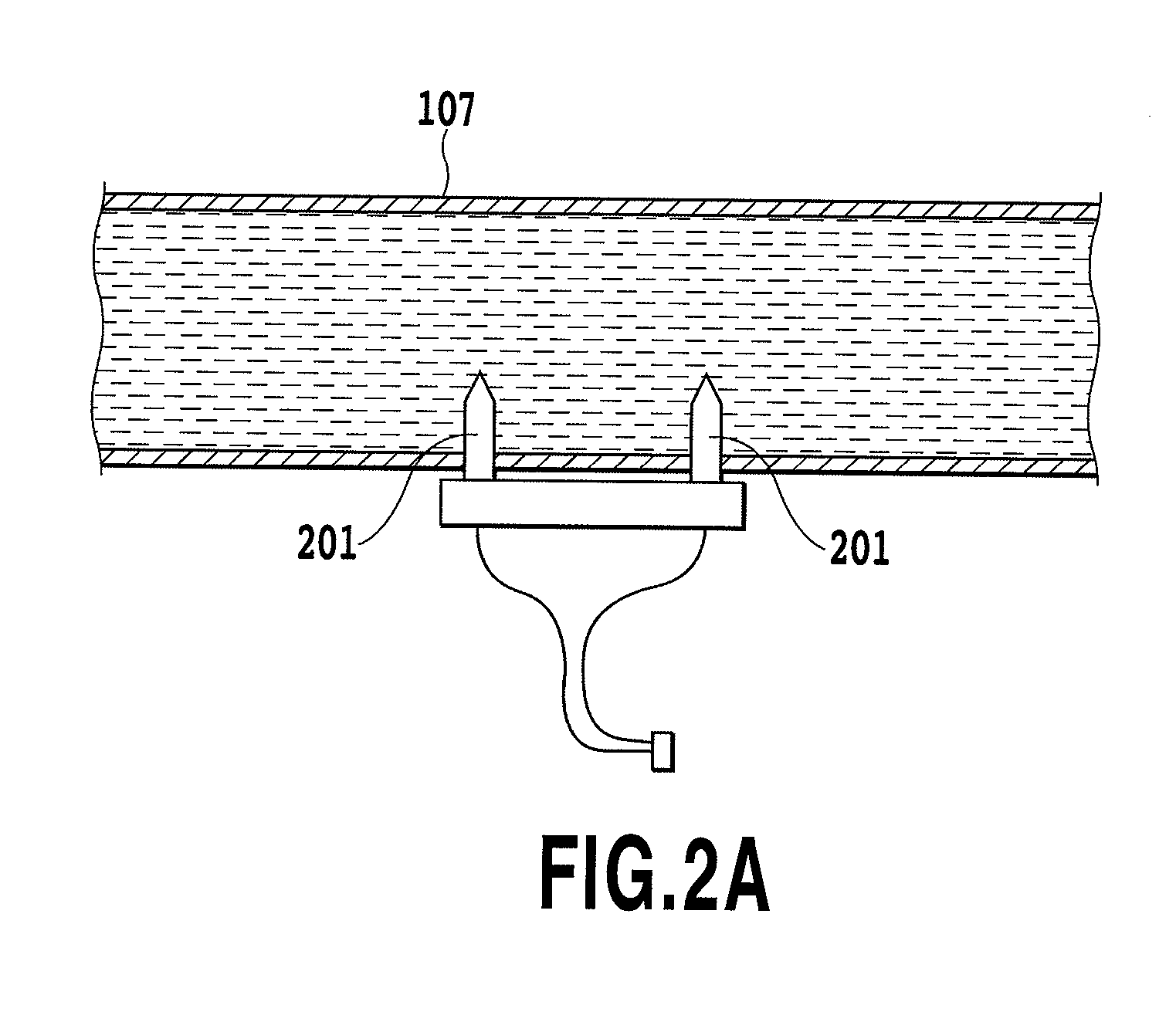
[0057]In the above described first to third embodiments, a pair of electrodes 201 are provided in the tube 107, and the amount and presence / absence of the liquid in the t...


PUM


Abstract

A voltage value detected at the time of filling the liquid changes in accordance with viscosity. The voltage value is used as an indicator of the viscosity of the liquid at the time of a returning operation. Specifically, when the voltage value acquired at the filling time is low, the viscosity is determined as relatively high at the time of the returning operation, and a returning threshold value Th1 is set to a relatively high value. In concrete, the filling voltage is updated each time a filling operation is performed, and as the value of the filling voltage which is referred to at the time of the returning operation, the value which is acquired in the immediately preceding filling operation is used. Thereby, even when the liquid has relatively high viscosity, completion of the returning operation can be detected without increasing the time required before completion of the returning operation.

Description

BACKGROUND OF THE INVENTION[0001]1. Field of the Invention[0002]The present invention relates to a liquid applying apparatus, and specifically relates to a structure for detecting the amount of a liquid used in the liquid applying apparatus.[0003]2. Description of the Related Art[0004]As a method for detecting the remaining amount of ink or the presence / absence of ink in an inkjet print apparatus, a method is widely known, in which a voltage value at the time of passing a current through the ink is measured by using a pair of electrodes. In such a method, the electric conductivity of the ink easily changes depending on the shapes of the electrodes, the contact state of the electrodes with a liquid, the structure and viscosity of the liquid, a temperature, or the like, and therefore, a technique in which effects of these factors can be suppressed to detect the remaining amount or the like with high precision has been proposed.[0005]Japanese Patent Laid-Open No. H03-270942 (1991) cite...

Claims


Application Information

Patent Timeline
IPC IPC(8): B05C1/08
CPCB05C1/0813B41J2202/12B41J2/0458B41J2/04571
Inventor KONDO, MITSURU
Owner CANON KK
Why Eureka
Try Eureka